

Nanometer mesoporous silicon based xerogel hemostatic material and its preparing method and use
一种纳米介孔、止血材料的技术,应用在化学仪器和方法、氧化硅、血液疾病等方向,能够解决覆盖、止血效果欠佳、使用过程复杂、组织热灼伤等问题,达到止血效果好、提高效果、加速愈合的效果
- Summary
- Abstract
- Description
- Claims
- Application Information
AI Technical Summary
Problems solved by technology
Method used
Image

Examples
Embodiment 1
[0040] Weigh 10 g of tetraethyl orthosilicate, dissolve in a mixed solvent of 5.4 g of deionized water and 2 g of absolute ethanol, mix and stir for 10 minutes; add 1N hydrochloric acid dropwise, keep the pH value at 3, and continue stirring for 2 hours. The sol was injected into a polyethylene mold and sealed for aging for 2 days, and then the temperature was gradually raised to 180° C. for 4 hours. Under an optical microscope, the synthesized silicon-based xerogel is a smooth, transparent block (see Figure 1). Further nitrogen adsorption-desorption test results show that the calcium-free silicon-based xerogel material has a pore size of 3nm and a specific surface area of 670m2 / g, denoted as L-1.
Embodiment 2
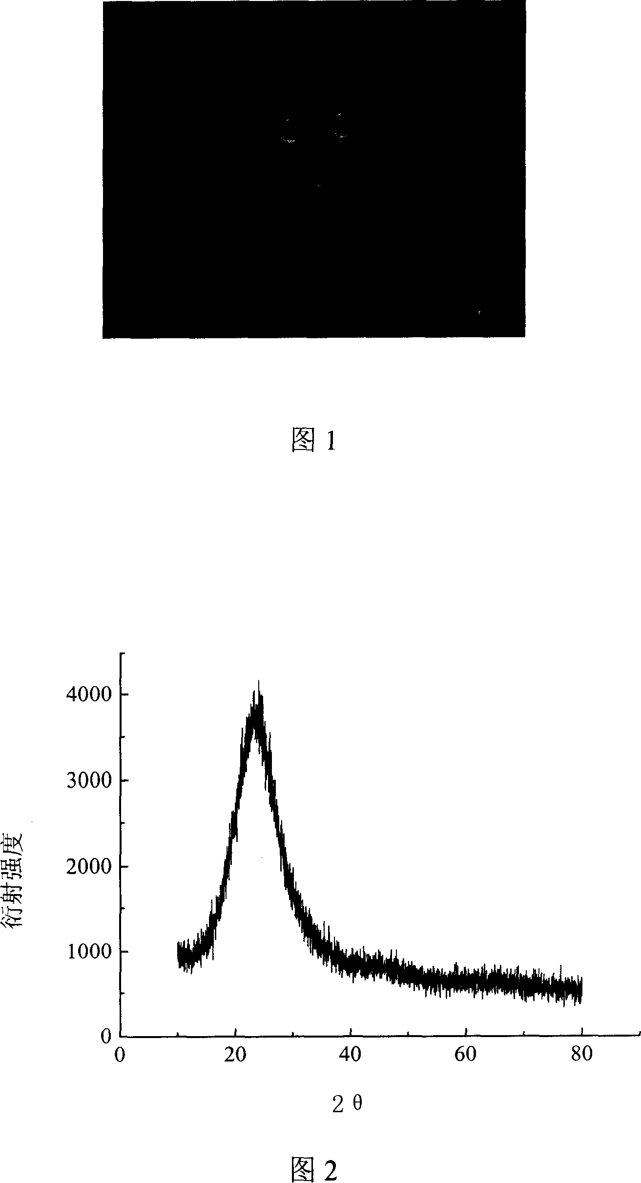
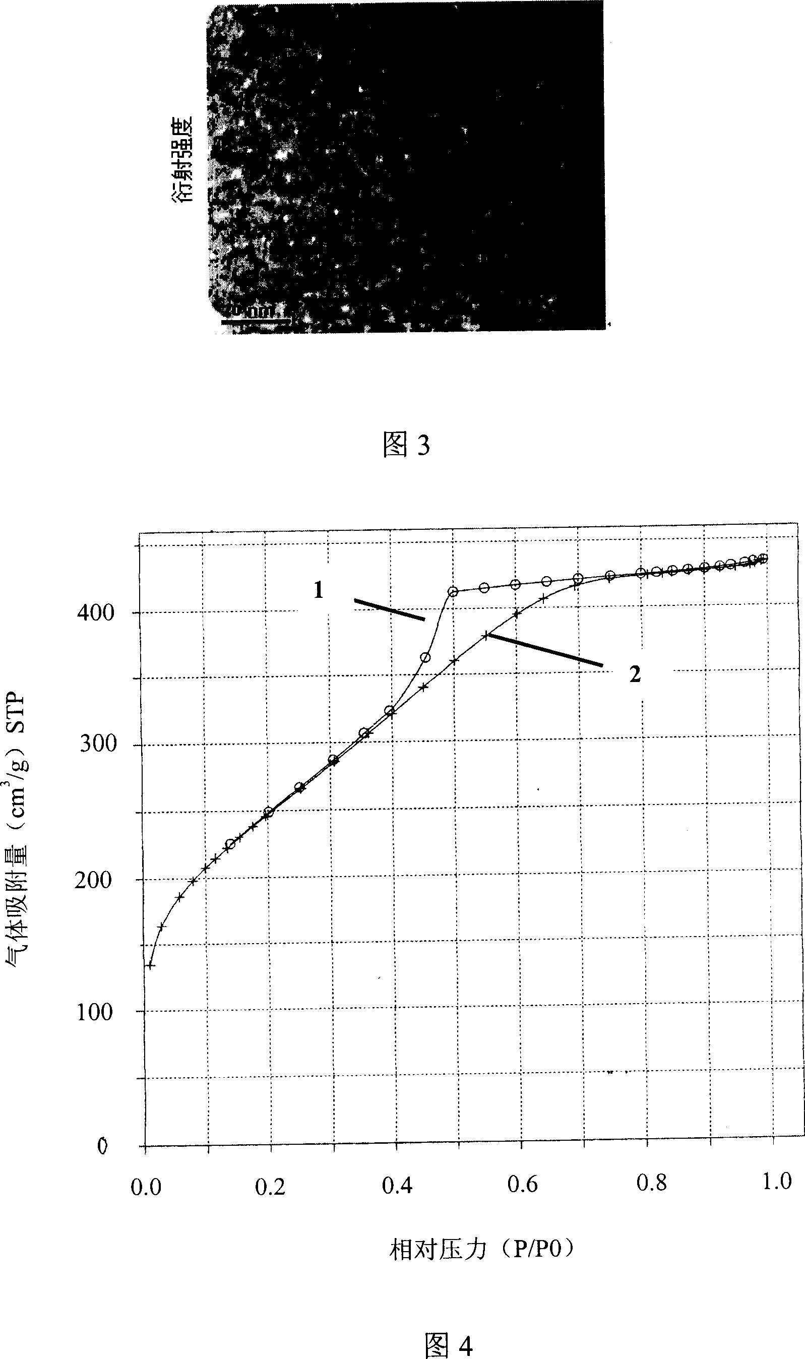
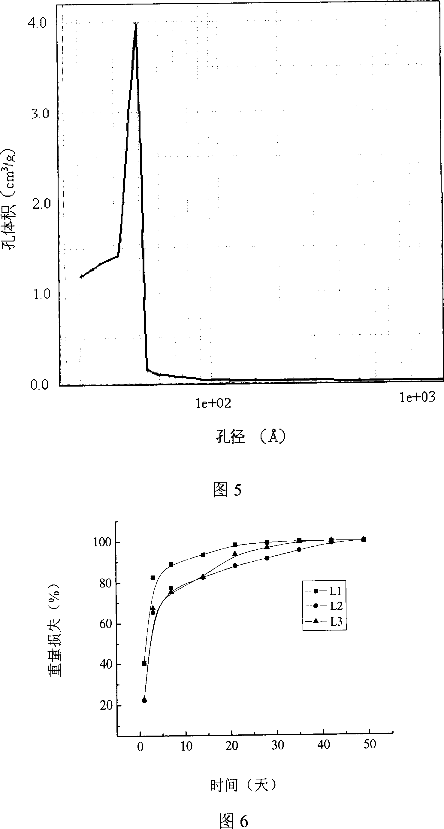
[0042] Weigh 10g ethyl orthosilicate, 3.36g trimethyl phosphate and 2.67g calcium chloride, dissolve in a mixed solvent of 8g deionized water and 8g absolute ethanol, mix and stir for 10 minutes at room temperature; add dropwise 1N hydrochloric acid, keep the pH value at 4, and keep stirring for 2 hours. The sol was injected into a polyethylene mold and aged in a sealed environment for 2 days, and then freeze-dried for 10 hours. The sample was put into a corundum crucible, heated to 700°C with a program-controlled electric furnace, cooled naturally, ground through a 150-mesh standard sieve, and sealed for later use. The powder is a calcium-containing silicon-based xerogel hemostatic material. Using X-ray diffractometer (XRD), scanning electron microscope (SEM) and BET method to test the phase composition, morphology, pore size and pore distribution of the prepared powder respectively, the results are shown in Figure 2, Figure 3, Figure 4, Figure 5. The results show that the...
Embodiment 3
[0044] Weigh 15g ethyl orthosilicate, 2.16g trimethyl phosphate and 1.71g calcium chloride, dissolve in a mixed solvent of 8g deionized water and 8g absolute ethanol, mix and stir for 10 minutes at room temperature, slowly drop Add 1N hydrochloric acid to keep the pH at 6, and continue stirring for 2 hours. The sol was injected into a polyethylene mold and aged in a sealed environment for 2 days, and then freeze-dried for 10 hours. The sample was put into a corundum crucible, heated to 700°C with a program-controlled electric furnace, cooled naturally, ground through a 150-mesh standard sieve, and sealed for later use. The powder is a calcium-containing silicon-based xerogel hemostatic material. Nitrogen adsorption-desorption experiment The powder has a pore size of 50nm and a specific surface of 650m 2 / g of calcium-containing silica-based xerogel, denoted as L-3.
PUM
 Abstract
Description
Claims
Application Information