
Implantable pump system having an undulating membrane with improved hydraulic performance

a technology of undulating membrane and implantable pump, which is applied in the field of implantable pump system with undulating membrane with improved hydraulic performance, can solve the problems of inability to pump oxygenated blood throughout the body, the walls of the ventricle are typically thick, and the left ventricle may be rendered less effective, so as to reduce hemolysis and platelet activation, the effect of low shear for

Active Publication Date: 2019-01-29
CORWAVE SA
View PDF169 Cites 12 Cited by
  • Summary
  • Abstract
  • Description
  • Claims
  • Application Information

AI Technical Summary

Benefits of technology

The present invention introduces an implantable pump system with a flexible membrane that can produce a wide range of flow rates while applying low shear forces to the blood, reducing damage to red blood cells and platelets compared to previous systems. The system has a unique design that allows the membrane to be suspended within a flow channel and guides blood evenly across the membrane, resulting in improved blood flow and reduced recirculation.

Problems solved by technology

Due to any of a number of illnesses, including coronary artery disease, high blood pressure (hypertension), valvular regurgitation and calcification, damage to the heart muscle as a result of infarction or ischemia, myocarditis, congenital heart defects, abnormal heart rhythms or various infectious diseases, the left ventricle may be rendered less effective and thus unable to pump oxygenated blood throughout the body.
In patients with systolic heart failure, the walls of the ventricle, which are typically thick in a healthy patient, become thin and weak.
For patients that have reached end stage heart failure, treatment options are limited.
While a cardiac transplant may significantly prolong the patient's life beyond the one year mortality rate, patients frequently expire while on a waitlist for months and sometimes years awaiting a suitable donor heart.
While in recent years mechanical implants have improved in design, typically such implants will prolong a patient's life by a few years at most, and include a number of co-morbidities.
Such pumps often are bulky, heavy and may require removal of bones and tissue in the chest for implantation.
They also require a significant amount of energy to displace the blood by compressing the cavity.
Moreover, the pump subjects the blood to significant pressure fluctuations as it passes through the pump, resulting in high shear forces and risk of hemolysis.
Further, depending on the geometry of the pump, areas of little or no flow may result in flow stagnation, which can lead to thrombus formation and potentially fatal medical conditions, such as stroke.
Finally, the positive displacement pumps like the one described in the Isaacson patent are incapable of achieving pulsatility similar to that of the natural heart, e.g., roughly 60 to 100 beats per minute, while maintaining physiological pressure gradients.
While previously-known LVAD devices have improved, those pump designs are not without problems.
Like reciprocating pumps, rotary and centrifugal pumps are often bulky and difficult to implant.
Rotary pumps, while mechanically different from positive displacement pumps, also exhibit undesirable characteristics.
Like positive displacement pumps, rotary pumps apply significant shear forces to the blood, thereby posing a risk of hemolysis and platelet activation.
The very nature of a disk or blade rotating about an axis results in areas of high velocity and low velocity as well as vibration and heat generation.
The resulting radial velocity profile along the rotating blade results in high shear forces being applied to the blood.
In addition, stagnation or low flow rates near the axis of rotation may result in thrombus formation.
While centrifugal pumps may be capable generating pulsatile flow by varying the speed of rotation of the associated disk or blades, this only exacerbates the problems resulting from steep radial velocity profiles and high shear force.
Accordingly, while centrifugal pumps can mimic a pulsatile flow with gradual speed changes, the resulting pulse is not “on-demand” and does not resemble a typical physiological pulse.
Moreover, rotary pumps typically result in the application of non-physiologic pressures on the blood.
Such high operating pressures have the unwanted effect of overextending blood vessels, which in the presence of continuous flow can cause the blood vessels to fibrose and become inelastic.
This in turn can lead to loss of resilience in the circulatory system, promoting calcification and plaque formation.
Further, if the rotational speed of a pump is varied to simulate pulsatile flow or increase flow rate, the rotary pump is less likely to be operated at its optimal operating point, reducing efficiency and increasing energy losses and heat generation.
While such systems can achieve flow rates as high as 8 or 9 liters per minute, these flow rates generally are outside of the efficient range of operation for current rotary pumps, which are typically tuned to operate in a range of 4 to 6 liters per minute.
Thus, increasing the flow rate in rotary pumps to match patient demanded results in non-optimal pump performance.
None of the foregoing patents to Drevet describe a vibratory membrane pump suitable for use in a biological setting, or capable of pumping blood over extended periods that present a low risk of flow stagnation leading to thrombus formation.
As a result, there is a risk of energy loss at the inlet to the membrane, which affects the hydraulic power generation by the pump.

Method used


Image

  • Implantable pump system having an undulating membrane with improved hydraulic performance
  • Implantable pump system having an undulating membrane with improved hydraulic performance
  • Implantable pump system having an undulating membrane with improved hydraulic performance

Examples


Embodiment Construction

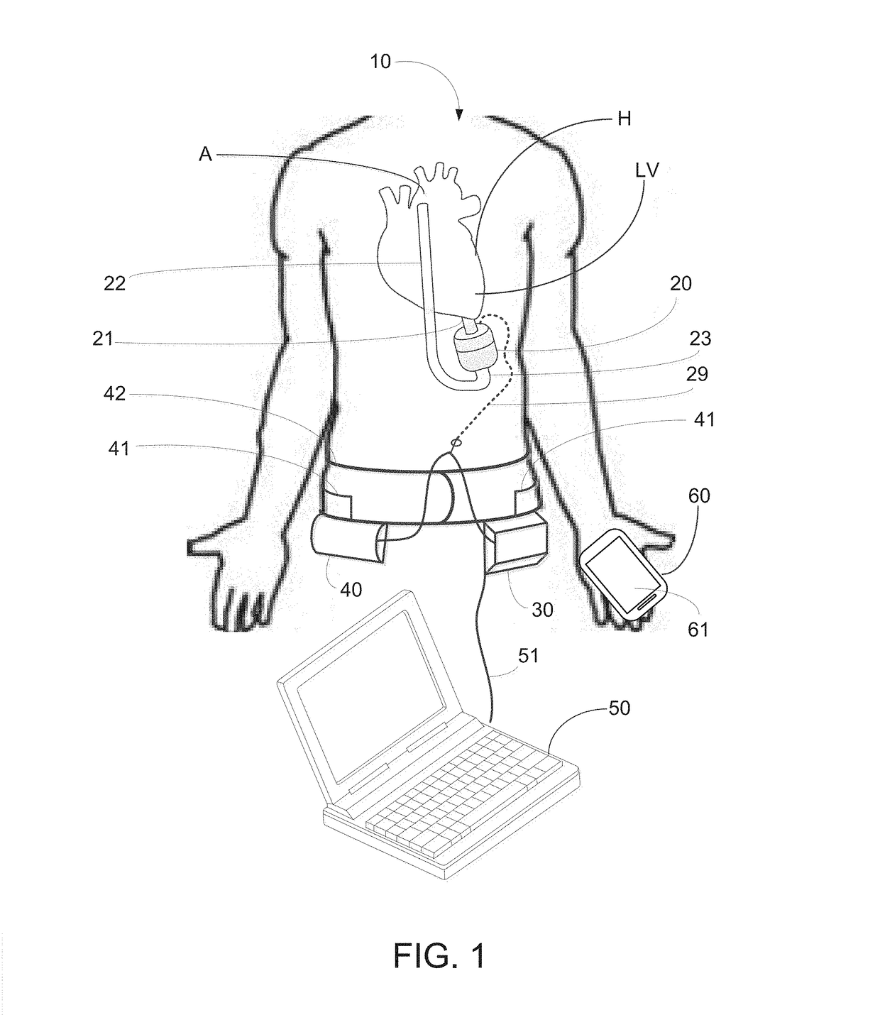
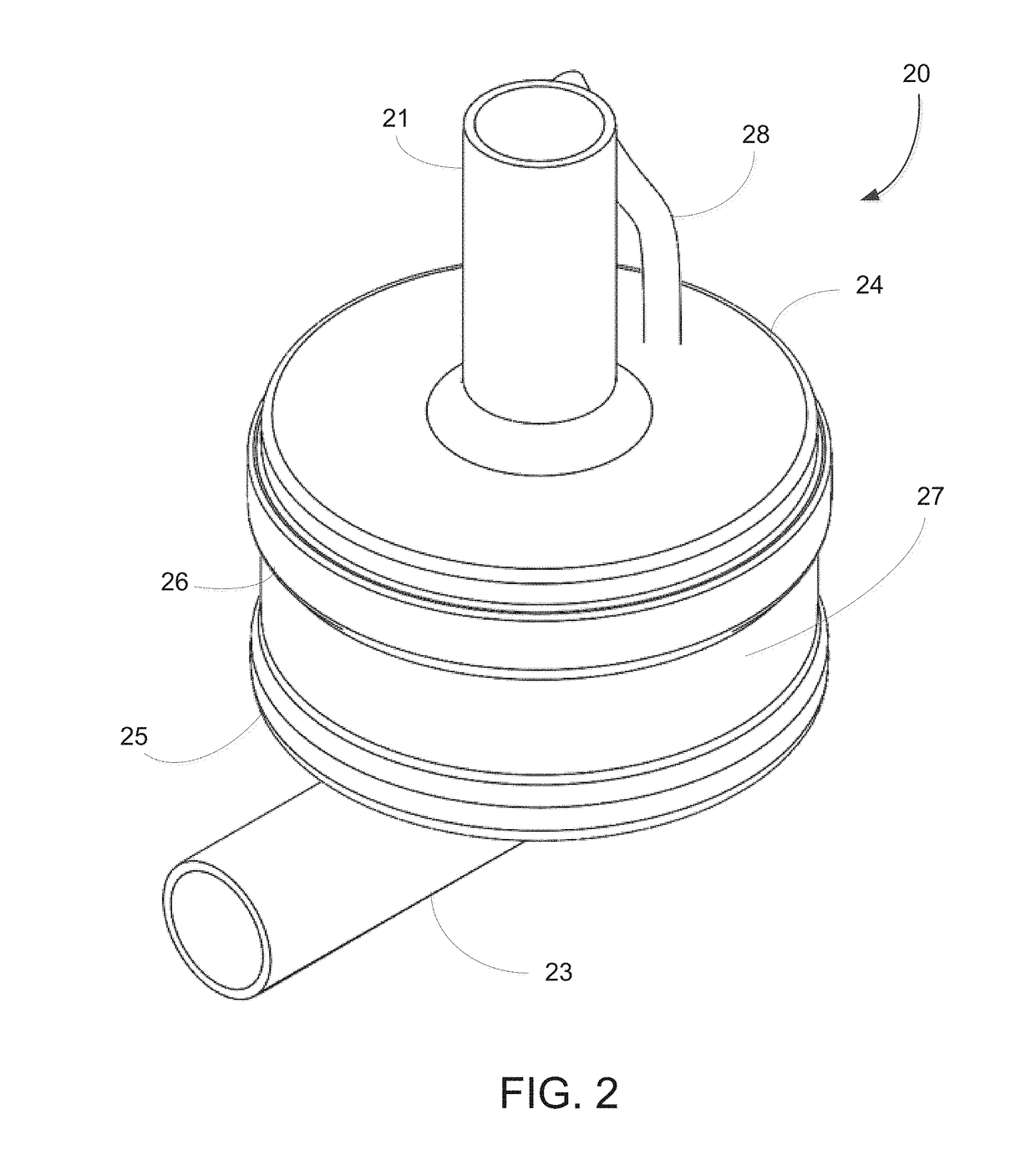
[0053]The implantable pump system of the present invention is particularly well-suited for use as a left ventricular assist device (LVAD), and includes an undulating membrane pump suitable for long-term implantation in a patient having end term heart failure. An implantable pump system constructed in accordance with the principles of the present invention includes an implantable pump and an extracorporeal battery, controller and programmer. The implantable pump includes a housing having an inlet, and outlet, a flexible membrane, and an actuator assembly. When configured as an LVAD, the housing includes an inlet cannula that is inserted into a patient's left ventricle near the apex and an outlet cannula that is surgically placed in fluid communication with the patient's aorta. By activating the actuator assembly within the implantable pump, membrane is induced to undulate, thereby causing blood to be drawn into the pump through the inlet cannula and expelled through the outlet cannul...


PUM


Abstract

An implantable pump system is provided, suitable for use as a left ventricular assist device (LVAD) system, having an implantable pump, a battery, a controller, and a programmer. The implantable pump includes a flexible membrane coupled to an actuator assembly via a skirt that extends toward the inlet of the pump and curves to guide blood toward the outlet. The actuator assembly is magnetically engagable with electromagnetic coils, so that when the electromagnetic coils are energized, the actuator assembly causes wavelike undulations to propagate along the flexible membrane to propel blood from the inlet, across the skirt, and through the outlet of the implantable pump. The controller may be programmed by a programmer to operate at frequencies and duty cycles that mimic physiologic flow rates and pulsatility while operating in an efficient manner that avoids thrombus formation, hemolysis and / or platelet activation.

Description

CROSS-REFERENCE TO RELATED APPLICATION[0001]This application claims priority to U.S. Provisional Application Ser. No. 62 / 592,359, filed Nov. 29, 2017, the entire contents of which are incorporated herein by reference.FIELD OF THE INVENTION[0002]The present invention relates generally to heart pumps and more particularly to implantable pumps having an undulating membrane with improved hydraulic performance designed to reduce hemolysis and platelet activation.BACKGROUND[0003]The human heart is comprised of four major chambers with two ventricles and two atria. Generally, the right-side heart receives oxygen-poor blood from the body into the right atrium and pumps it via the right ventricle to the lungs. The left-side heart receives oxygen-rich blood from the lungs into the left atrium and pumps it via the left ventricle to the aorta for distribution throughout the body. Due to any of a number of illnesses, including coronary artery disease, high blood pressure (hypertension), valvular...

Claims


Application Information

Patent Timeline
IPC IPC(8): A61M1/12A61M1/10A61M60/178A61M60/268A61M60/427A61M60/508A61M60/837A61M60/857
CPCA61M1/122A61M1/1036A61M1/1008A61M1/1086A61M2205/581A61M2209/088A61M2205/3523A61M2205/587A61M2205/18A61M2205/8206A61M5/14276A61M5/14224A61M60/268A61M60/857A61M60/427A61M60/178A61M60/508A61M60/837A61M60/148A61M60/419A61M60/122A61M60/457A61M60/459A61M60/462A61M60/50A61M60/40
Inventor POLVERELLI, LUCMAINE, LEOPOLDBOTTERBUSCH, CARL N.LUCQUIN, SILVEREDREVET, JEAN-BAPTISTEGUIGNABERT, ADRIENMENEROUD, PATRICKSCHMIDT, ALEXANDRAMONTICONE, PIER-PAOLO
Owner CORWAVE SA
Learn More