R-T-B based rare earth magnet

a rare earth magnet and rtb technology, applied in the field of rare earth magnets, can solve the problems of small improvement in property stability, and achieve the effects of reducing the b-rich phase to be formed, reducing the range of sintering temperature, and reducing the property stability

Active Publication Date: 2020-11-03
TDK CORPARATION
View PDF8 Cites 0 Cited by
  • Summary
  • Abstract
  • Description
  • Claims
  • Application Information

AI Technical Summary

Benefits of technology

[0007]When the B content is set to be lower than the stoichiometric ratio in R2T14B and the amount of the B-rich phase to be formed is decreased as described in Patent Document 1, the property stability is lowered, and the range of the sintering temperature at which suitable properties can be obtained is narrowed. It is also possible to improve the property stability by adding a compound of a heavy rare earth element(s) having a high melting point as described in Patent Document 2. However, since the compound having a high melting point reacts with a liquid phase in the sintering process, the compound melts down during the sintering process, so the effect of improving the property stability is not large.
[0008]An object of the present invention is to obtain an R-T-B based rare earth magnet which has improved magnetic properties and a wide optimal temperature range for the sintering.
[0010]With the above configuration, the R-T-B based rare earth magnet of the invention improves the magnetic properties and has a wide optimal temperature range for sintering.

Problems solved by technology

However, since the compound having a high melting point reacts with a liquid phase in the sintering process, the compound melts down during the sintering process, so the effect of improving the property stability is not large.

Method used


Image

  • R-T-B based rare earth magnet
  • R-T-B based rare earth magnet
  • R-T-B based rare earth magnet

Examples


example 1

[0080]First, alloy A having the composition described in the following Table 1 was prepared by a strip casting method.

[0081]Subsequently, the alloy A was subjected to a hydrogen pulverization treatment (coarse pulverization) to obtain coarse pulverized powder A. Specifically, hydrogen was absorbed at room temperature to the raw material alloy, and then dehydrogenation was performed at 600° C. for one hour in Ar gas atmosphere.

[0082]Next, 0.1 mass % of oleic acid amide as a pulverization aid was added to the coarse pulverized powder A, and mixed thereof using a Nauta mixer. Thereafter, fine pulverization was carried out by a jet mill using N2 gas to obtain finely pulverized powder A having a particle diameter D50 of approximately 4.0 μm.

[0083]Addition alloy “a” having the composition described in Table 2 below was prepared. The additive alloy “a” was prepared by arc melting the raw material metal, melting at high frequency, and subjecting it to a solution treatment. The arc melting w...

example 2

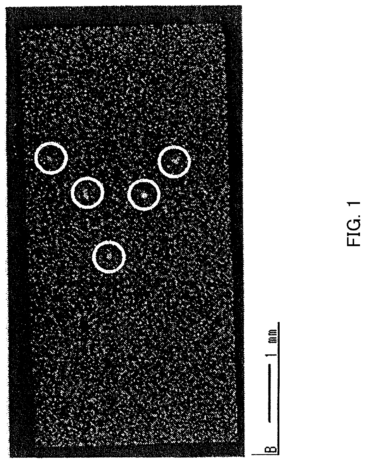
[0091]Among the sintered bodies of Example 1, the sintered body having the highest sintering temperature among the sintered bodies having Hk / HcJ of 95% or more, that is, the sintered body having the sintering temperature of 1060° C. was cut out to a rectangular parallelepiped shape of 10 mm×7.0 mm×3.5 mm. At this time, the direction of the 3.5 mm side was set to be the direction in which the magnetic field was applied during the pressing in the magnetic field.

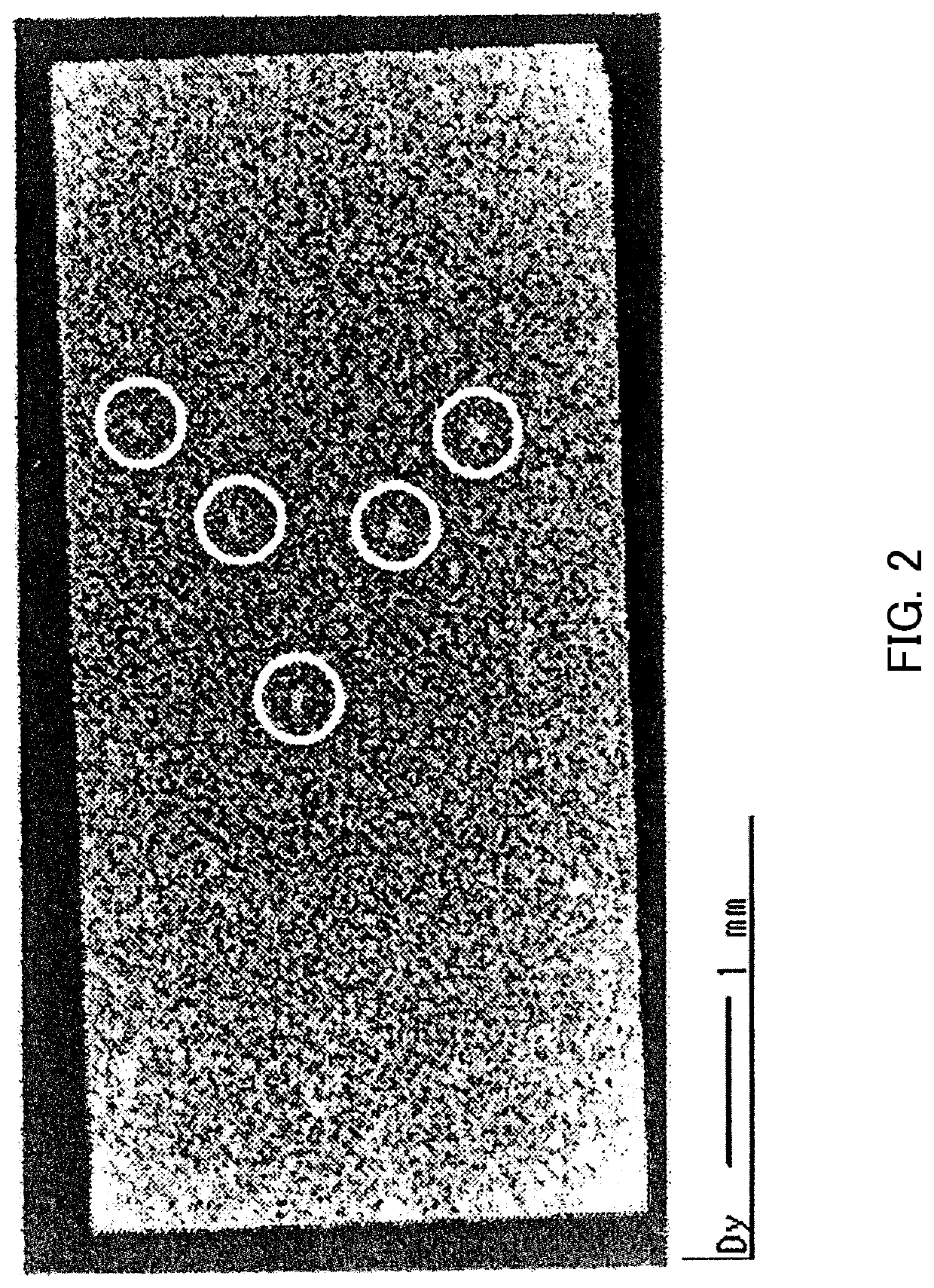
[0092]Next, the rectangular parallelepiped shaped sintered body was subjected to Dy diffusion. A detailed method of the diffusion is described below.

[0093]Pretreatment of the diffusion process was carried out to the rectangular parallelepiped shaped sintered body by performing the following treatment twice. The treatment includes an immersion in a mixed solution of nitric acid and ethanol for three minutes and a subsequent immersion in ethanol for one minute. After the pretreatment, the sintered body was washed and dried.

[0094]...

examples 21 to 33

[0113]The results conducted under the same conditions with Example 2, except alloy A was changed to alloys A1 to A13 shown in Table 6, are shown in Examples 21 to 33 in Tables 7 and 8.

[0114]

TABLE 6Nd[massPrDyAlCoCuGaZrMnBFe%][mass %][mass %][mass %][mass %][mass %][mass %][mass %][mass %][mass %][mass %]Alloy A22.06.51.40.320.10.10.050.040.88bal.Alloy A128.50.01.40.320.10.10.050.040.88bal.Alloy A221.06.51.40.320.10.10.050.040.88bal.Alloy A325.06.51.40.320.10.10.050.040.88bal.Alloy A422.06.51.40.0320.10.10.050.040.88bal.Alloy A522.06.51.40.420.10.10.050.040.88bal.Alloy A622.06.51.40.320.010.10.050.040.88bal.Alloy A722.06.51.40.320.30.10.050.040.88bal.Alloy A822.06.51.40.320.10.10.030.040.88bal.Alloy A922.06.51.40.320.10.10.70.040.88bal.Alloy A1022.06.51.40.320.10.10.050.010.88bal.Alloy A1122.06.51.40.320.10.10.050.10.88bal.Alloy A1222.06.51.40.30.10.10.10.050.040.88bal.Alloy A1322.06.51.40.330.10.10.050.040.88bal.

[0115]

TABLE 7NdPrDyTbAlCo[mass[mass[mass[massR in total[mass[massCuGaZr...


PUM

PropertyMeasurementUnit
equivalent circle diameteraaaaaaaaaa
circle diametersaaaaaaaaaa
equivalent circle diametersaaaaaaaaaa

Abstract

Provided is an R-T-B based rare earth magnet. R is one or more rare earth elements, T is one or more transition metal elements essentially including Fe or Fe and Co, and B is boron. B content with respect to a total R-T-B based rare earth magnet is 0.80 mass % or more and 0.98 mass % or less. The R-T-B based rare earth magnet includes an R1T4B4 phase.

Description

BACKGROUND OF THE INVENTION1. Field of the Invention[0001]The present invention relates to an R-T-B based rare earth magnet.2. Description of the Related Art[0002]R-T-B based rare earth magnets have been used in a wide variety of fields since they show superior magnetic properties, and in recent years, the field of the use has been increasing more due to dramatic improvement of the magnetic properties of R-T-B based rare earth magnets. In the market, further improvement is expected for the magnetic properties of R-T-B based rare earth magnets.[0003]For instance, Patent Document 1 describes an R-T-B based rare earth magnet having a composition with a low B (boron) content. It is stated that a B-rich phase is not formed by lowering the B content, and a magnet having a high residual magnetic flux density is obtained. In concrete, making the B content in the R-T-B based magnet represented by R2T14B to a level slightly lower than the stoichiometric ratio in R2T14B, the amount of the B-ri...

Claims


Application Information

Patent Timeline
Patent Type & Authority Patents(United States)
IPC IPC(8): H01F1/057C22C38/04C22C38/06C22C38/14C22C38/16C22C38/00C22C30/02C22C38/10B22F3/24B22F3/26B22F9/02B22F9/04B22F1/00B22F1/05
CPCC22C38/10C22C38/005C22C38/06H01F1/057C22C38/14C22C30/02H01F1/0577C22C38/16C22C38/002C22C38/04B22F2304/10B22F2003/247B22F2301/355B22F3/26B22F2003/242B22F2998/10B22F1/0011B22F9/023B22F2999/00C22C2202/02B22F2009/045B22F2009/044B22F9/04B22F2207/13B22F5/00C22C33/0257B22F3/02B22F3/10B22F2003/248B22F1/05
Inventor IWASAKI, MAKOTOHIDAKA, TETSUYAKATO, EIJIHAYAKAWA, TAKUMAKITAOKA, HIDETAKE
Owner TDK CORPARATION
Why Eureka
Try Eureka