Analysis method of molecular interactions on protein nanoparticles using flow cytometry

a technology of molecular interactions and flow cytometry, which is applied in the field of molecular interactions on protein nanoparticles using flow cytometry, can solve the problems of emulsion destruction, limited protein size to be displayed on the mrna-ribosome, and limited stability of ribosome complexes and technical sensitivity, so as to improve the screening efficiency and improve the signal-to-noise ratio , the effect of easy analysis

Active Publication Date: 2021-02-02
KOREA RES INST OF BIOSCI & BIOTECH
View PDF11 Cites 0 Cited by
  • Summary
  • Abstract
  • Description
  • Claims
  • Application Information

AI Technical Summary

Benefits of technology

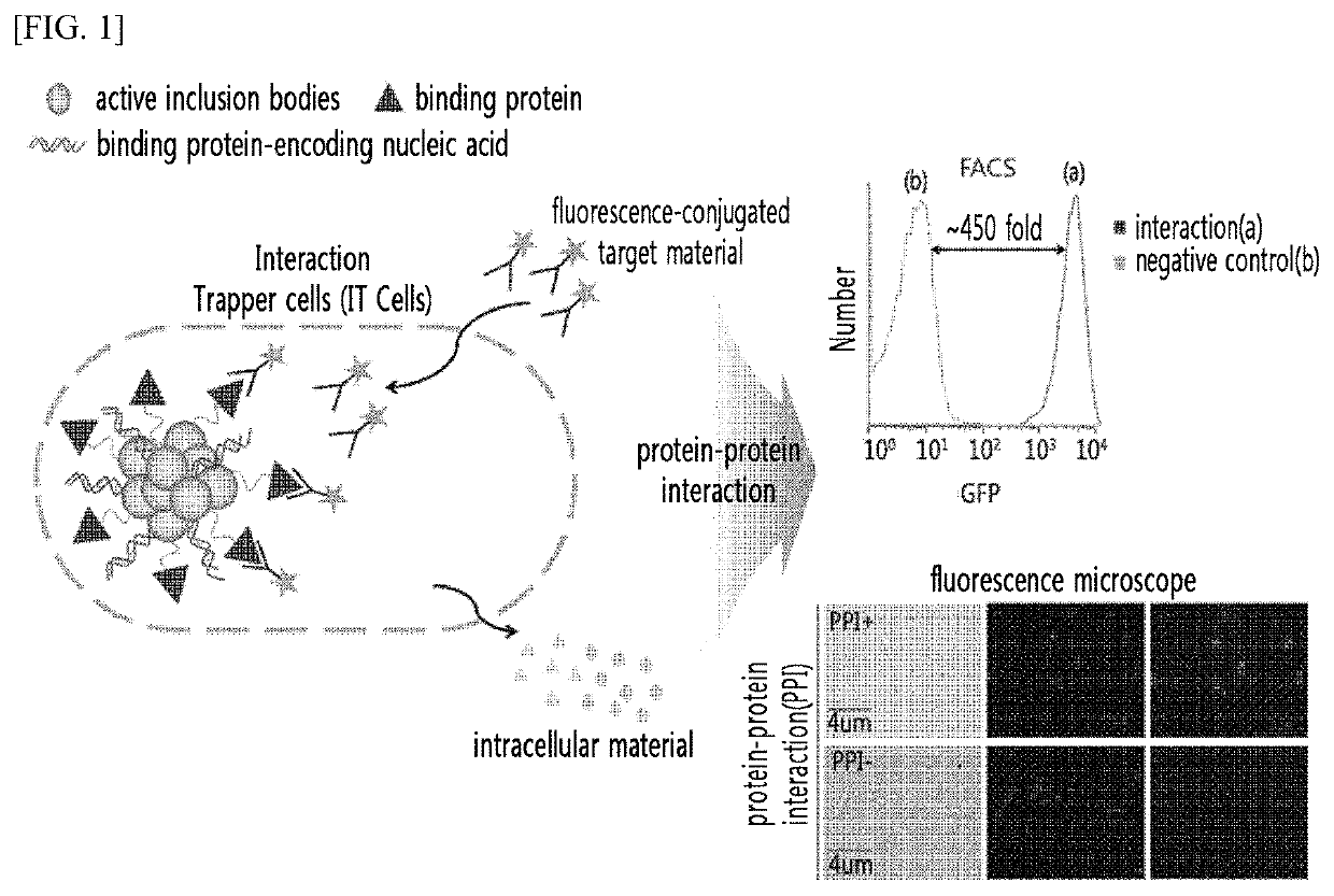
[0026]The method of the present invention enables a sensitive labeling of a target material, which interacts due to the overexpression of a binding protein, and thereby provides an improved screening efficiency due to a significantly higher signal-to-noise ratio (a 450-fold increase) compared to the conventional screening methods. The method of the present invention also enables easy isolation of cells by an individual cell unit, and thus can provide a high-throughput screening (HTS) technology to screen and isolate interacting proteins from a large number of libraries using a fluorescence microscope and a flow cytometer. Additionally, the interactions between biomolecules in any foreign target material with difficulty of in-vivo expression can be readily analyzed at high speed by introduction thereof into cells after extracellular expression. The present invention can be used in various fields, including the development of antibodies / artificial antibodies, preparation of novel interacting proteins, and analysis and optimization of the interactions between target proteins and drug candidates.BRIEF DESCRIPTIONS OF THE DRAWINGS
[0027]FIG. 1 shows the representative drawing of the present invention illustrated in a schematic diagram, which shows the intracellular particle display enabling high-speed analysis between materials and the results of analysis of interactions between materials using the same.
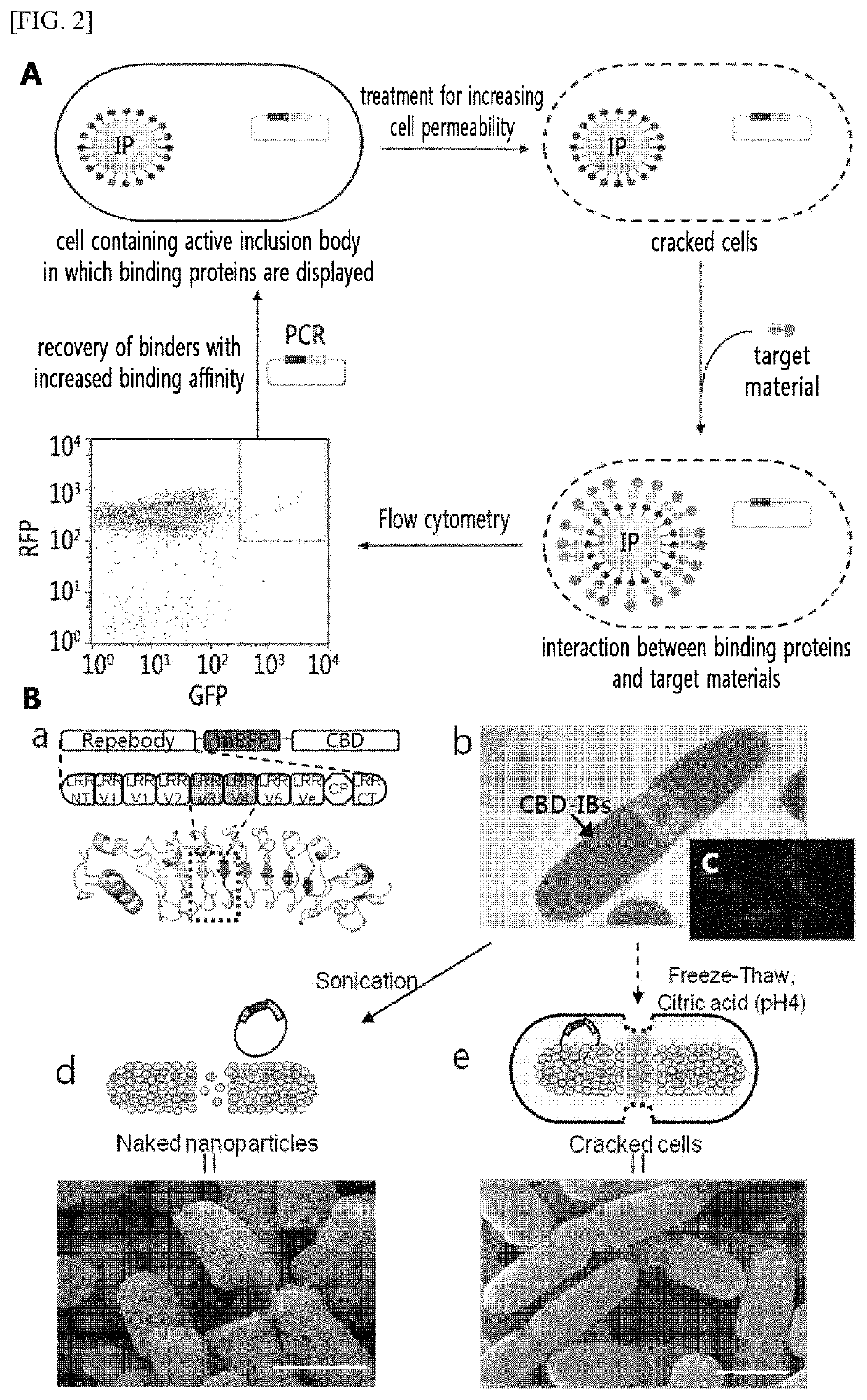
[0028]In FIG. 2, A shows an entire schematic diagram of intracellular particle display technique from the methodological point of view. Additionally, in B of FIG. 2, the ‘a’ shows a schematic diagram, in which a binding protein (repebody) and a red fluorescent protein (mRFP) are fused and displayed in active inclusion bodies; the ‘b’ shows an electron microscope image of cells, in which the protein inclusion bodies (CBD-IBs) of the ‘a’ are expressed; and the ‘c’ shows a fluorescence microscope image of cells, in which the protein inclusion bodies of the ‘a’ were expressed (blue: genomic DNA). Additionally, the ‘d’ shows a schematic diagram of the protein inclusion bodies isolated from the cells of the ‘b’ by ultrasonication; and the ‘e’ shows a schematic diagram illustrating the generation of cracks in the cells when they underwent the process of increasing cell permeability according to the method of the present invention.
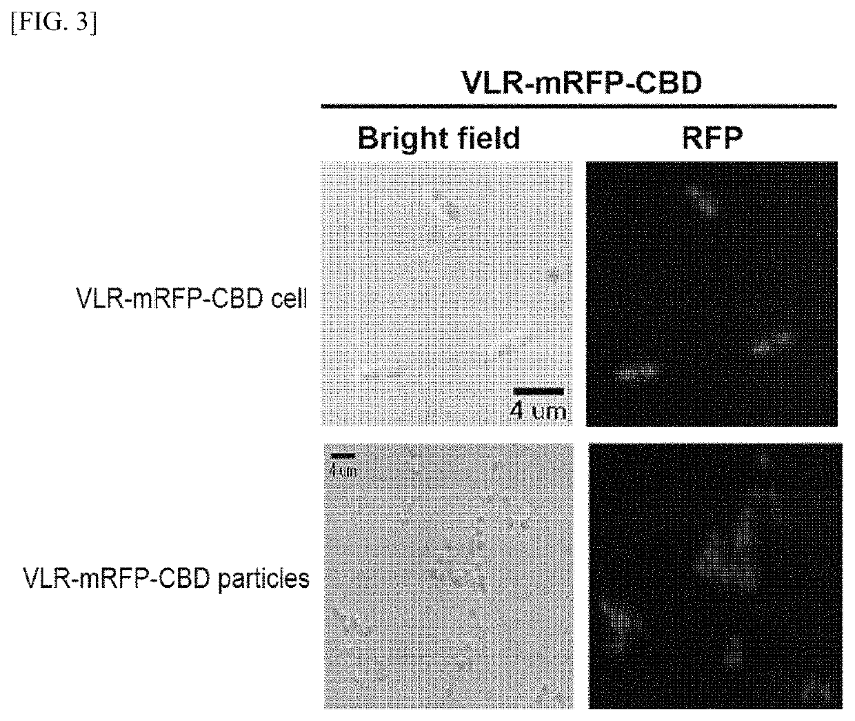
[0029]FIG. 3 shows fluorescence microscope images of the interaction trapper (IT) cells, in which a binding protein (VLR) and a fluorescent protein (mRFP) are displayed using a CBD protein capable of forming active inclusion bodies, and only the inclusion bodies isolated from the IT cells by ultrasonication
[0030]FIG. 4 shows the results of flow cytometry analysis, confirming the effect of a cell-thawing / freezing process developed in the present invention on increasing cell permeability according to the presence / absence of active inclusion body display of the binding protein.
[0031]FIG. 5 shows the results of flow cytometry analysis, confirming that the cell freezing process during the process developed in the present invention for increasing cell permeability, could maintain the activity and expression of the binding protein displayed on the active inclusion bodies, but it was not sufficient to introduce a foreign target material.

Problems solved by technology

Any problem in the control of the interaction can influence the entire network and may cause a disease.
However, there are disadvantages in that only 27% is present as complexes, and the protein size to be displayed on the mRNA-ribosome is limited, and there are limits in terms of stability of ribosome complexes and technical sensitivity, etc.
However, the emulsion can be destroyed using an organic solvent during protein recovery, and the organic solvent used may reduce the activities of proteins, and the thus-recovered proteins may not exhibit activities in-vivo (Dan S. Tawfik and Andrew D. Griffiths, 1998.
However, since 1 to 5 binding proteins are displayed on the pIII protein of phage and a target is used after immobilizing it to beads and plate bottom, several bindings may occur simultaneously, thereby causing an avidity effect, i.e., a problem showing a difference in the real affinity of an individual protein to the target.
In this regard, there is a limit in that the displayed protein cannot be easily eluted from the immobilized phase when the displayed protein has a high binding affinity to the target.
Additionally, the panning method used for screening libraries in phage display has a limit in that it has a low signal-to-noise ratio, and thus at least 3 to 5 panning processes are required for obtaining proteins having binding affinity to the target.
Further, there is a limit in that it has a high false positive rate (George P. Smith and Valery A. Petrenko, 1997.
However, the above method has limits in that it only allows observation of the interactions between intracellular biomolecules expressed simultaneously in-vivo.
Furthermore, due to its low signal-to-noise ratio, it is difficult to effectively compartmentalize and recover the binding material as an individual cell unit after it has interacted with the target material.
Additionally, the method has a limit in that the target material must be limited to materials that can be synthesized in cells, such as proteins, peptides, nucleic acids, etc., and that only fluorescent proteins must be used as the fluorescence signal.
That is, the method has disadvantages in that various forms of target materials introduced from the outside cannot be used, and that various kinds of fluorescent chemical materials cannot be used.

Method used


Image

  • Analysis method of molecular interactions on protein nanoparticles using flow cytometry
  • Analysis method of molecular interactions on protein nanoparticles using flow cytometry
  • Analysis method of molecular interactions on protein nanoparticles using flow cytometry

Examples


example 1

nt of Genes and Enzymes

[0147]A cellulose-binding domain (CBD, SEQ ID NO: 15) gene of family II was cloned using the exoglucanase gene of Cellulomonas fimi KCTC 9143 strain obtained from the Korean Collection of Type Cultures (KCTC). The improved modified green fluorescent protein (mGFP, SEQ ID NO: 16) gene was obtained from the pEGFP (Clontech, CA, USA), a commercial vector, and the plasmid vector pRFP including the mRFP1 (monomeric red fluorescent protein 1, SEQ ID NO: 17) gene was provided by the Korea Advanced Institute of Science and Technology (KAIST) (Daejeon, Korea). Among the repebody (InB-VLR) family (artificial antibody protein), which is an artificial protein where the N-terminus of internaline B (InB) protein, a modified repeat module of a variable lymphocyte receptor (VLR) protein, and the C-terminus of VLR protein are conjugated, In-VLR5c (Korean Patent Application Publication No. 10-2010-0086055, SEQ ID NO: 18), which has no binding affinity for IL6; and In-VLR5c-D3E8...

example 2

ion of a Recombinant Vector

[0148]All of the primers used in the present invention were synthesized by Bioneer Corporation (Daejeon, Korea). The primers are shown in Table 1 below. The restriction sites such as NdeI and KpnI are indicated in bold in Table 1. All genes used in the present invention were amplified using each of the primers shown in Table 1, conjugated by overlap extension PCR, inserted into the NdeI and HindIII restriction sites of pET21a vector, and recombined using E. coli DH5a cells. The thus-prepared plasmid vectors were designated as pInVLR5c-mRFP-CBD, pD3E8-mRFP-CBD, pF11-mRFP-CBD, pGFP-IL6, respectively. Additionally, the pInVLR5c-mRFP-CBD plasmid, after treating with the restriction enzymes of NdeI and HindIII, was inserted into the pET21a vector, which was treated with NdeI and HindIII, and recombined using E. coli DH5a cells. The thus-prepared plasmid vector was designated as pInVLR5c-mRFP.

[0149]

TABLE 1Primer NameSequence (5′→3′)SEQ ID NOndeI histag VLR FGGAA...

example 3

solation

[0151]The pInVLR5c-mRFP-CBD, pD3E8-mRFP-CBD, pF11-mRFP-CBD, and pInVLR5c-mRFP plasmids prepared in Example 2 were transformed into E. coli DH5a, inoculated into LB medium (1% bacto-trypton, 0.5% yeast extract, and 1% NaCl) containing ampicillin (50 μg / mL), and incubated in a shaking incubator at 37° C. for 24 hours. The cultured cell suspension was centrifuged at 4,470×g for 5 minutes using a centrifuge (Universal 320R, Hettich), and the plasmids were isolated from the pellet freed from the supernatant using the QIAprep® spin miniprep kit, and the isolated plasmids were confirmed on a 1% agarose gel by electrophoresis.

[0152]Additionally, the pGFP-IL6 plasmid prepared in Example 2 was transformed into E. coli DH5a, inoculated into LB medium (1% bacto-trypton, 0.5% yeast extract, and 1% NaCl) containing ampicillin (50 μg / mL), and incubated in a shaking incubator at 37° C. for 24 hours. The cultured cell suspension was centrifuged at 4,470×g for 5 minutes using a centrifuge (Un...


PUM

PropertyMeasurementUnit
temperatureaaaaaaaaaa
pHaaaaaaaaaa
volumeaaaaaaaaaa

Abstract

The present invention relates to a method for analyzing the interaction between a binding protein and a target material, including measuring the interaction between the binding protein and a target material using an interaction trapper (IT) cell. The IT cell has the binding protein displayed on the surface of intracellular inclusion bodies, i.e., insoluble aggregates, by expressing a fusion protein which forms active protein particles containing the binding protein. The method includes increasing cell permeability without affecting the activity of the binding protein displayed on the cells and genetic information.

Description

TECHNICAL FIELD[0001]The present invention relates to a method for analyzing the interaction between a binding protein and a target material, including measuring the interaction between the binding protein and the target material using an interaction trapper (IT) cell. The IT cell has the binding protein displayed on the surface of intracellular inclusion bodies, i.e., insoluble aggregates, by expressing a fusion protein which forms active protein particles containing the binding protein. The method includes increasing cell permeability without affecting the activity of the binding protein displayed on the active inclusion bodies and genetic information. Additionally, the present invention relates to a method for screening a library, further including a step of recovery by an individual cell unit. Furthermore, the present invention is characterized by introducing a target material from the outside of a cell thereinto while conserving genetic information and the activity of the bindi...

Claims


Application Information

Patent Timeline
Patent Type & Authority Patents(United States)
IPC IPC(8): G01N33/68G01N33/58
CPCG01N33/6803G01N33/582G01N33/68C40B30/04C40B40/02
Inventor LEE, SEUNG-GOOKIM, YU JUNGGAM, JONGSIKKIM, HASEONGLEE, DAE-HEEJUNG, HEUNG-CHAE
Owner KOREA RES INST OF BIOSCI & BIOTECH
Why Eureka
Try Eureka