Process and catalyst for reducing nitrogen oxides

a technology of nitrogen oxides and catalysts, applied in the direction of nitrogen purification/separation, inorganic chemistry, exhaust treatment, etc., can solve the problems of toxic vanadium compounds at elevated exhaust gas temperatures, high catalyst activity, and high catalyst activity

a technology of nitrogen oxides and catalysts, applied in the direction of nitrogen purification/separation, inorganic chemistry, exhaust treatment, etc., can solve the problems of toxic vanadium compounds at elevated exhaust gas temperatures, high catalyst activity, and high catalyst activity

US20020039550A1Inactive Publication Date: 2002-04-04UMICORE AG & CO KG

Image

  • Process and catalyst for reducing nitrogen oxides
  • Process and catalyst for reducing nitrogen oxides
  • Process and catalyst for reducing nitrogen oxides

Examples


Embodiment Construction

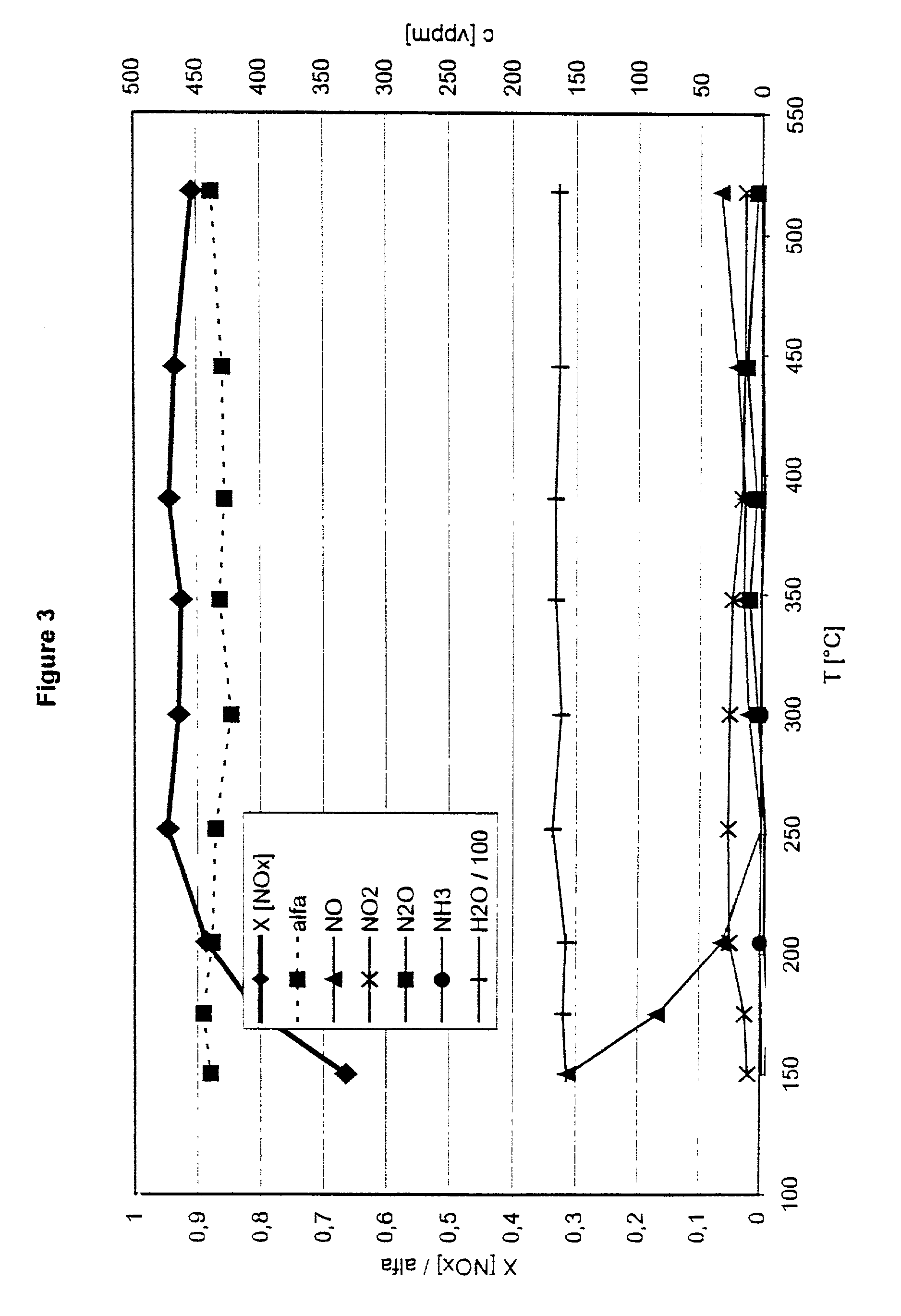
[0039] Drilled cores of these catalysts with a diameter of 2.54 cm and a length of 7.62 cm were subjected to the following synthesis gas mixture at a space velocity of 30000 h.sup.-1 to test them in the process according to the invention:

1 500 Vol.ppm nitrogen oxides in the ratio NO:NO.sub.2 of 1:1; 3:1 and 1:3 450 Vol.ppm ammonia 5 Vol. % oxygen 1.3 Vol. % water vapour Remainder, nitrogen

[0040] The temperature of the synthesis gas was increased in steps from 150 to 525.degree. C. For each temperature step, the gas composition was analysed downstream of the reduction catalyst.

[0041] FIG. 3 gives the results for a freshly prepared catalyst. The volume ratio NO / NO.sub.2 in this case was 1:1.

[0042] FIGS. 4 to 6 show the experimental results for aged catalysts. To age the catalysts, they were stored for a period of 48 hours under hydrothermal conditions at a temperature of 650.degree. C.

[0043] FIG. 4 shows the results for a volume ratio NO / NO.sub.2 of 3:1, FIG. 5 for a volume ratio NO / N...


PUM

PropertyMeasurementUnit
temperaturesaaaaaaaaaa
concentrationaaaaaaaaaa

Abstract

A process for reducing the nitrogen oxides present in a lean exhaust gas from an internal combustion engine by selective catalytic reduction on a reduction catalyst using ammonia, wherein a fraction of the nitrogen monoxide present in the exhaust gas is oxidized to nitrogen dioxide before the exhaust gas, together with ammonia, is passed over the reduction catalyst. The reduction catalyst contains a zeolite exchanged with transition metals and oxidation of the nitrogen monoxide is performed in such a way that the exhaust gas contains 30 to 70 vol. % of nitrogen dioxide before contact with the reduction catalyst.

Description

INTRODUCTION AND BACKGROUND[0001] The present invention relates to a process for reducing the nitrogen oxides present in a lean exhaust gas produced from an internal combustion engine by selective catalytic reduction on a reduction catalyst using ammonia, wherein a fraction of the nitrogen monoxide present in the exhaust gas is oxidized to nitrogen dioxide before the exhaust gas, together with ammonia, is passed over the reduction catalyst.[0002] The process of selective catalytic reduction (SCR=selective catalytic reduction) has been used for a long time in the power station sector to reduce the nitrogen oxides present in the flue gases from a power station. The flue gases from power stations have a net oxidizing effect due to the high proportion of oxygen. The nitrogen oxides present therein can therefore be reduced to nitrogen only with difficulty. This problem was solved by so-called selective catalytic reduction, in which the flue gas is mixed with ammonia and passed over a sui...

Claims


Application Information

Patent Timeline
04 Apr 2002
Publication
US20020039550A1
IPC
B01D53/34; B01D53/56; F01N3/08; B01D53/74; B01D53/86; B01D53/94; B01J8/02; B01J21/00; B01J23/80; B01J29/06; B01J29/064; B01J29/072; B01J29/076; B01J29/46; B01J35/04; B01J37/02; B01J37/30; C01B21/00; C01B21/04; F01N3/10; F01N3/20; F01N3/28
CPC
B01D53/9418; Y02T10/24; B01D2251/2067; B01D2255/2065; B01D2255/20738; B01D2255/20761; B01D2255/504; B01D2255/808
Inventors
SCHAFER-SINDLINGER, ADOLF; PFEIFER, MARCUS