

Electrochemical cell stacks
a technology of electrochemical cells and stacks, applied in the field of electrochemical cells, can solve the problems of large space occupation, inefficient use of overall space or footprint, and large space occupation of electrode spacing,
Inactive Publication Date: 2002-08-01
KIRK DONALD W +2
View PDF0 Cites 49 Cited by
- Summary
- Abstract
- Description
- Claims
- Application Information
AI Technical Summary
Benefits of technology
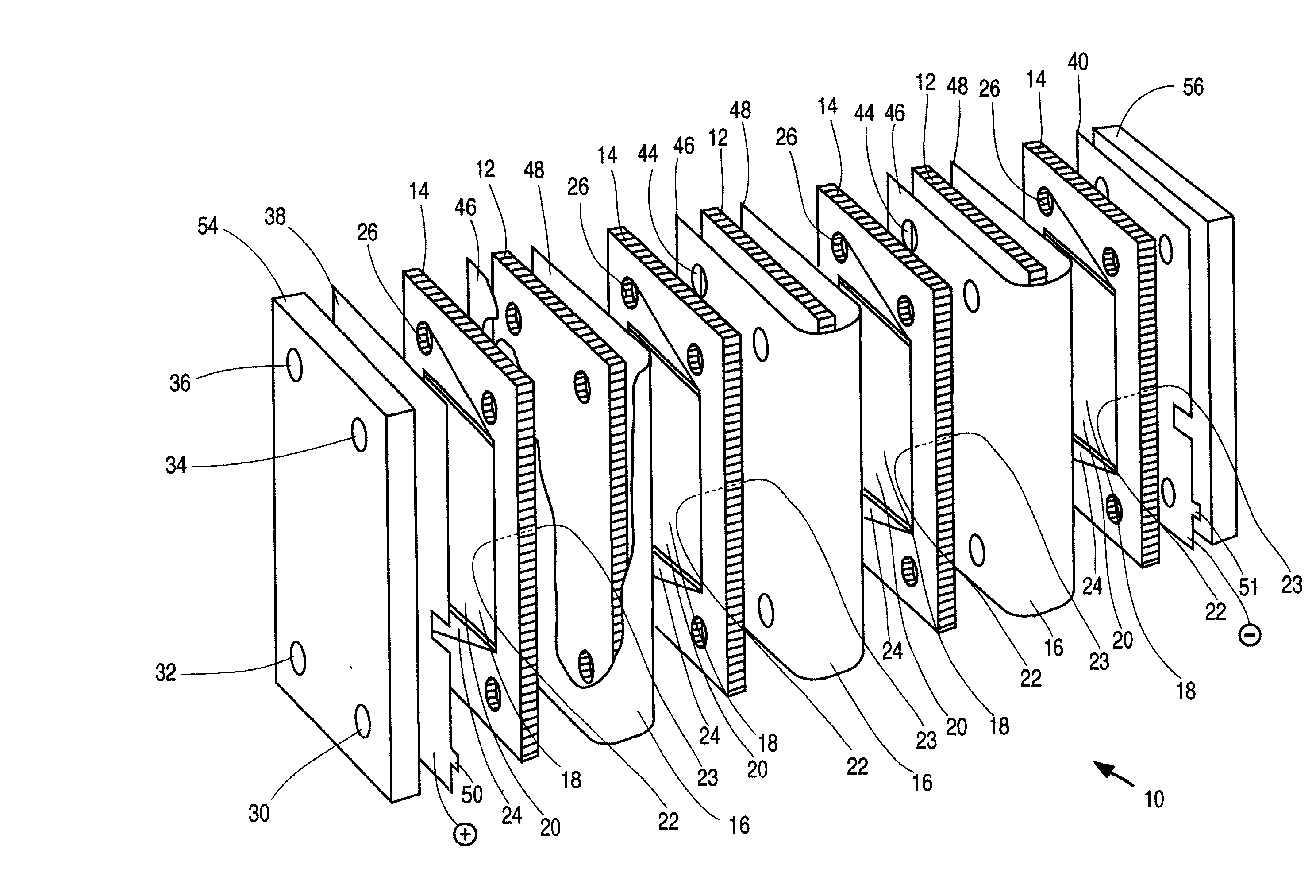
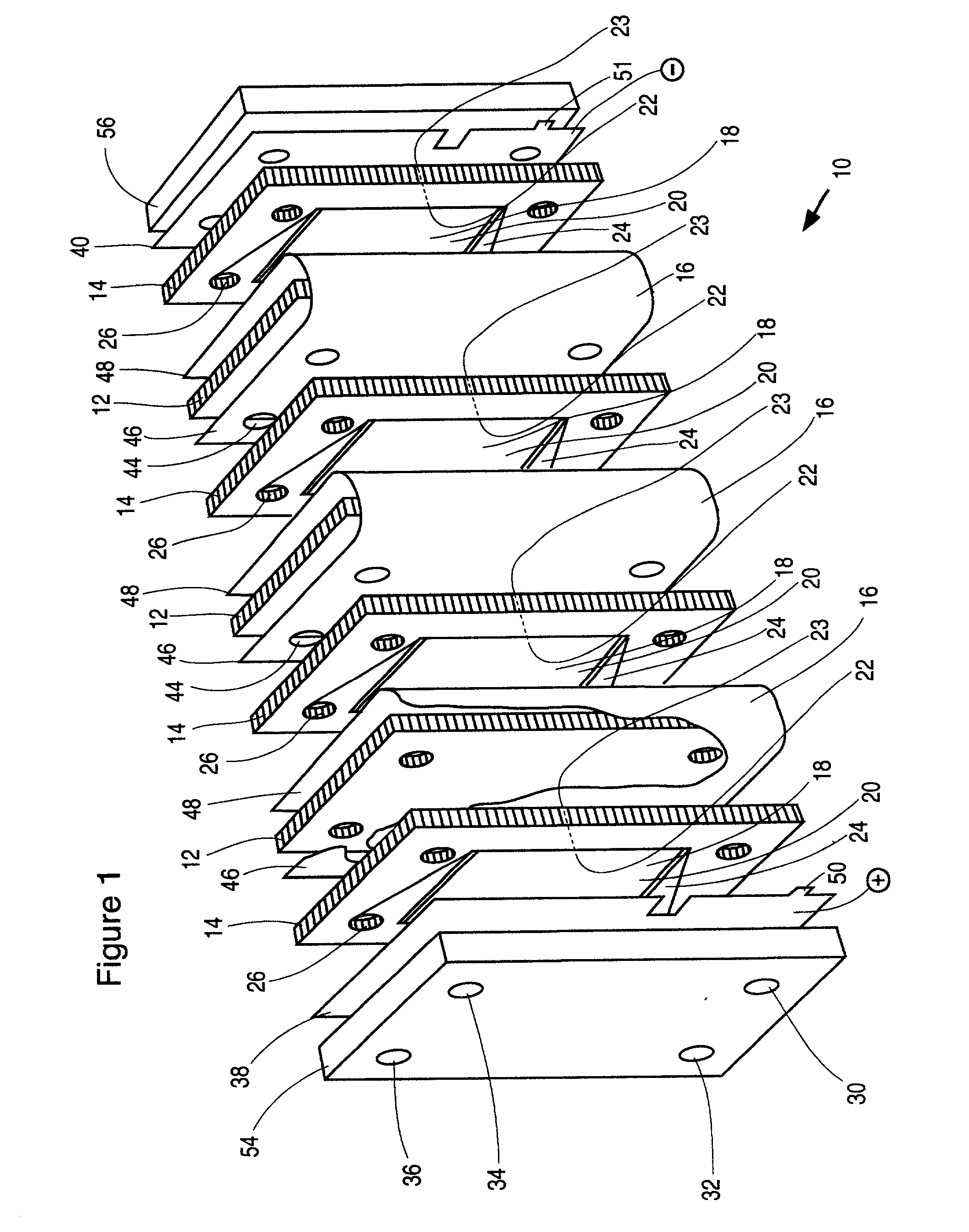
[0014] The production of a bilayer or trilayer porous assembly offers the distinct advantages of minimal electrode / membrane thickness and, hence, inter-electrode cell resistance, as well as ease of processing on a continuous basis by the integration of separate parts, namely, current carrier+activation+membrane, using known, suitable processing methods.
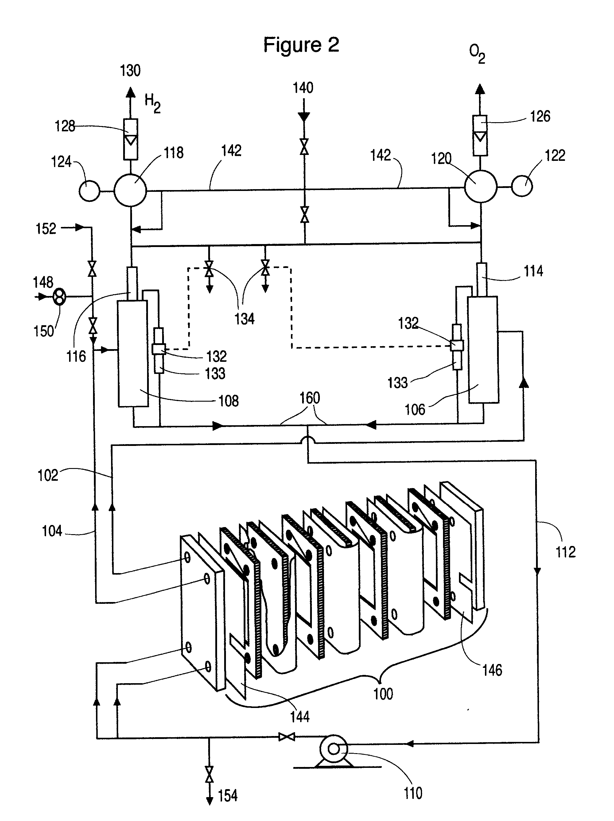
[0053] The level of the liquid in the, respective, gas liquid separator is used as the first indicator of the pressure differential in the cell stack. The pressure control of the system must allow the liquid levels to stay equal or within some small level of tolerance supported by the membrane. Although electronic control systems may be used to adjust pressure regulators a more direct method is, preferred, involving a matched pair of back pressure regulators--one for oxygen and one for hydrogen. These back pressure regulators are controlled by a common, single compressed gas pressure source. This common single compressed gas always provides the same release pressure to both regulators automatically regardless of the control pressure. With this device the primary pressure balance control is assured. Operation of the cells with this configuration shows exceptionally stable pressure balance during many hours of operation, even at high current density >600 mA / cm.sup.2 and temperatures up to 100.degree. C. This control of pressure balance is achieved without the continuous control adjustment that is required by electronic control systems. Furthermore, no sensor input is required for this control and, thus, adds a high level of security to the system.
Problems solved by technology
There is no integration of the cell itself as the pressure containment device, and, thus, the apparatus is bulky and heavy.
However, the apparatus requires the need for a tank to house cells and, thus, this does not represent efficient use of overall space or footprint.
The cylindrical configuration of the anodes and cathodes present fabrication challenges and the spacing of these electrodes will require substantial room to prevent non-uniform currents if multiple cells are used.
Again, this is clearly not a design suitable for lightweight and inexpensive polymeric materials.
With regard to the spent electrolyte ports, with the preferred design having thin foil electrodes, it is not possible to provide a seal against the unsupported electrodes which are facing the upper portion of the frame member defining a triangle having an apex defining a catholyte exit port or anolyte exit port channel.
In another configuration (bipolar) described later, this alternating seal configuration is not sufficient for preventing electrolyte mixing and a stiffer electrode must be used to allow for a seal on one side of the electrode at the exit port.
The production of hydrogen from prior art monopolar cell stacks has been limited to current densities of less than about 500 mA / cm.sup.2 at steady state operation.
The primary problem is that at high current density the volume of gas produced at the electrode surfaces becomes so great that cell resistance rises dramatically, liquid contact with the electrode surface is reduced and parts of the electrode may cease to function, unsteady liquid and gas flows develop and energy efficiency decreases dramatically.
Resistive heating exacerbates the problems causing electrode heating and damage to cell components which renders the cell dangerous to operate.
It would be expected that at high current density (>500 mA / cm.sup.2) resistive heating in the thin foil electrodes and from the resistance in the electrolyte due to gas formation, would cause this type of cell to fail.
Without valving, the cell could not be run at more than 250 mA / cm.sup.2 before excessive gassing caused unstable operation and damaging resistive heating.
2. The smaller volume of gas also allows operation at higher current densities than is the case at lower pressures where the large volume of gas would form plugs within the cell compartment resulting in unstable operation or preventing electrolysis altogether.
This decreases the size of the electrolyte channels required, the capacity of the pump, and the erosion and wear on all components of the cell caused by the high linear velocity of flowing electrolyte.
A first attempt used a 0.635 cm steel plate in addition to a glass- filled polyphenylene oxide backing plate but this was of insufficient stiffness to allow complete sealing to take place within the cell stack.
Both gaskets and o-rings are made of elastomers which distort easily under stress and thus provide no structural strength for pressure resistance.
If sufficient tension from the tie rods is applied to allow friction to hold the gasket or frame member in place, then the gasket or frame member becomes so compressed that their structural function is lost.
Gasket seals, particularly with slippery caustic solutions, are quite susceptible to seal "bowout" if the stack pressure rises.
In industrial practice, manual adjustment is not desirable for continuous operation.
Method used
View moreImage
Smart ImageViewing Examples

Examples
example
[0116] A partial stack according to FIG. 1 has been operated typically at 50 A, 67 psig and 95.degree. C. with an electrolyte flow rate of 0.8 L / min per cell. The voltage required is 2.15 V per cell indicating an energy efficiency of 69.4% based on the higher heating value of hydrogen. With a common electrolyte return, the current efficiency is 97.5% and the hydrogen production rate is 22.2 standard L / h per cell.
Login to View More PUM
| Property | Measurement | Unit |
|---|---|---|
| pressure | aaaaa | aaaaa |
| pressure | aaaaa | aaaaa |
| pressure | aaaaa | aaaaa |
Abstract
An electrochemical cell stack comprising stack walls and a plurality of electrolytic cells within the stack walls, each cell comprising cell members selected from an anode a cathode; a membrane separator frame formed of a non-conductive material and having a frame first planar peripheral surface; a frame second planar peripheral surface; and a central portion defining a membrane-receiving aperture; a membrane within the aperture to provide an anolyte circulation chamber and a catholyte circulation chamber distinct one from the other within the frame, an impermeable cell end wall formed of a non-conductive material between the anode and cathode and the anodes and cathodes of adjacent cells of said stack; wherein each of said anode, said cathode, said separator frame and said end wall has a portion defining an anolyte flow inlet channel, a catholyte flow inlet channel, a spent anolyte channel and a spent catholyte channel; said anolyte flow inlet channel and said spent anolyte channel are in communication with said anolyte circulation chamber, said catholyte flow inlet channel and said spent catholyte channel are in communication with said catholyte circulation chamber. The cell stack is of greatly reduced footprint, operable at relatively high temperatures and pressures and which is stable under current load.
Description
[0001] This invention relates to electrochemical cell stacks, particularly, to monopolar filter press cell stacks, and more particularly to internally pressurized monopolar water electrolytic cells for the production of hydrogen and oxygen.BACKGROUND TO THE INVENTION[0002] Electrosynthesis is one example of an electrochemical process comprising a method for the production of chemical reaction(s) that is electrically driven by passage of an electric current, typically a direct current (DC), in an electrochemical cell through an electrolyte between an anode electrode and a cathode electrode from an external power source. The rate of production is proportional to the current flow in the absence of parasitic reactions. For example, in a liquid alkaline water electrolysis cell, the DC current is passed between the two electrodes in an aqueous electrolyte to split water, the reactant, into component product gases, namely, hydrogen and oxygen where the product gases evolve at the surfaces ...
Claims
Login to View More Application Information
Patent Timeline
 Patent Type & AuthorityApplications(United States)
IPC IPC(8): C25B9/20C25B15/02
CPCC25B9/20C25B15/02C25B9/73C25B1/04C25B9/75
InventorKIRKGRAYDON, JOHN W.THORPE
OwnerKIRK DONALD W