Protective coating for a thermally stressed component, particularly a turbine component

a technology for thermal stress components and protective coatings, which is applied to wind motor components, non-positive displacement fluid engines, liquid fuel engine components, etc., can solve the problems of increasing the concentration of alloy impurities, reducing the life of the component to be protected, and limited life of such protective coatings

Inactive Publication Date: 2002-09-19
ALSTOM (SWITZERLAND) LTD
View PDF0 Cites 34 Cited by
  • Summary
  • Abstract
  • Description
  • Claims
  • Application Information

AI Technical Summary

Problems solved by technology

The life of such a protective coating is however limited, since the protective aluminum oxide layer continues to grow, so that more and more aluminum is withdrawn from the protective coating.
The life of the component to be protected then also decreases, due to the damage to the protective coating.
For example, an increased concentration of allo

Method used


Image

  • Protective coating for a thermally stressed component, particularly a turbine component
  • Protective coating for a thermally stressed component, particularly a turbine component

Examples


first embodiment

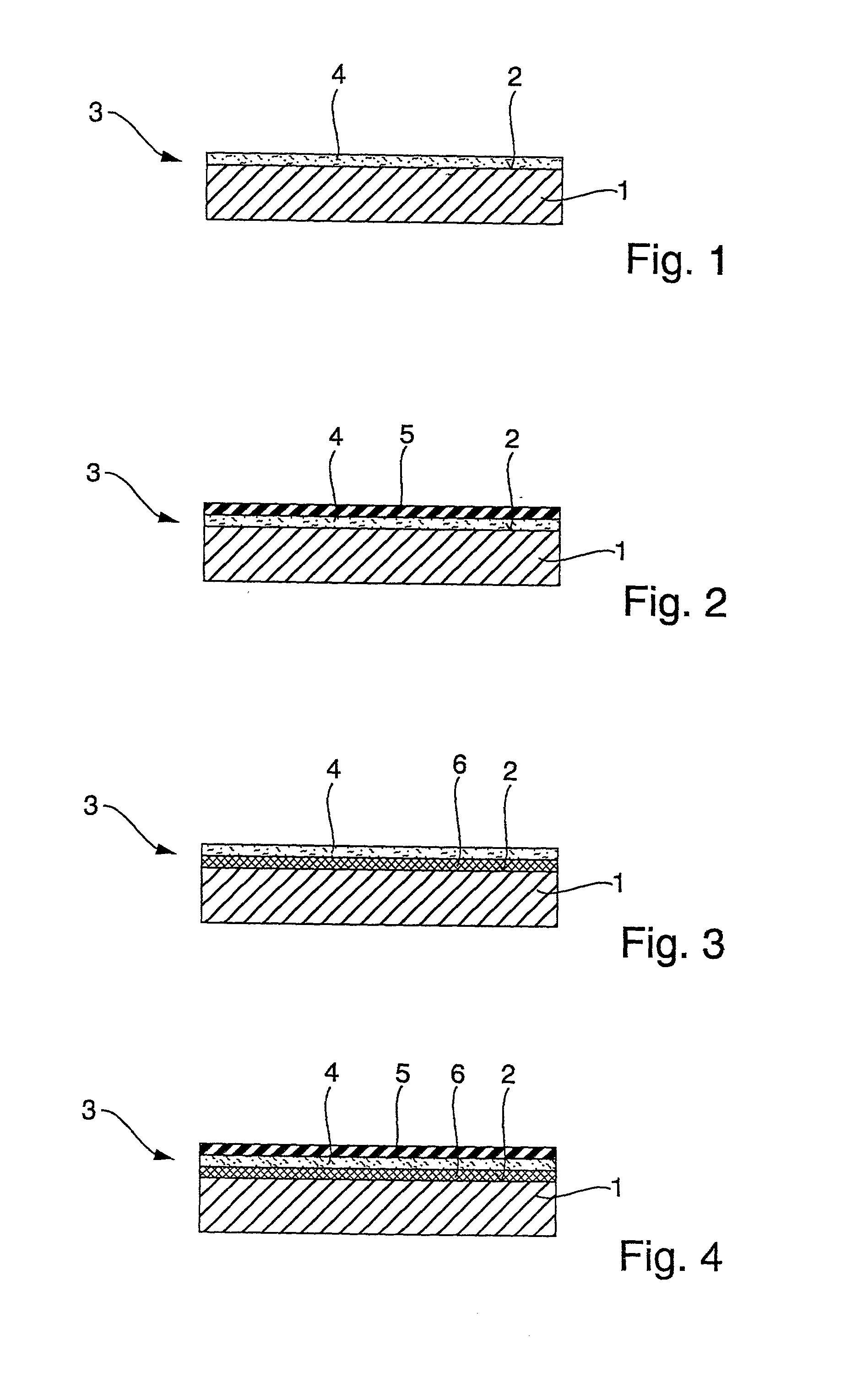
[0022] According to FIG. 1, the protective coating 3 according to the invention in a first embodiment consists exclusively of the sealing coating 4, which correspondingly is arranged directly on the surface 2 of the component 1. The sealing coating 4, preferably of amorphous aluminum oxide or amorphous silicon carbonitride, can for example be applied to the component 1 by a physical vapor deposition process (PVD process) or by a chemical vapor deposition process (CVD process). A laser PVD process or a laser CVD process are preferred. The material of the component 1 is thus effectively protected from the attack of aggressive media by the protective coating 4, so that the component 1 has an increased service life.

second embodiment

[0023] According to FIG. 2, the protective coating 3 according to the invention in a second embodiment has a heat insulating coating 5 in addition to the sealing coating 4. While the sealing coating 4 is arranged on the surface 2 of the component 1, the heat insulating coating 5 is situated on the sealing coating 4. The heat insulating coating 5 can for example consist of a stabilized zirconium oxide, which is appropriately applied by air plasma spraying, flame spraying, or by an electron beam PVD process, as a single layer or a multilayer. The temperature of the sealing coating 4 and also of the component 1 can be reduced by the heat insulating coating 5, in order, for example, to be able to ensure given required mechanical properties, e.g., stability, rigidity, or extension behavior of the sealing coating 4 or of the component 1.

third embodiment

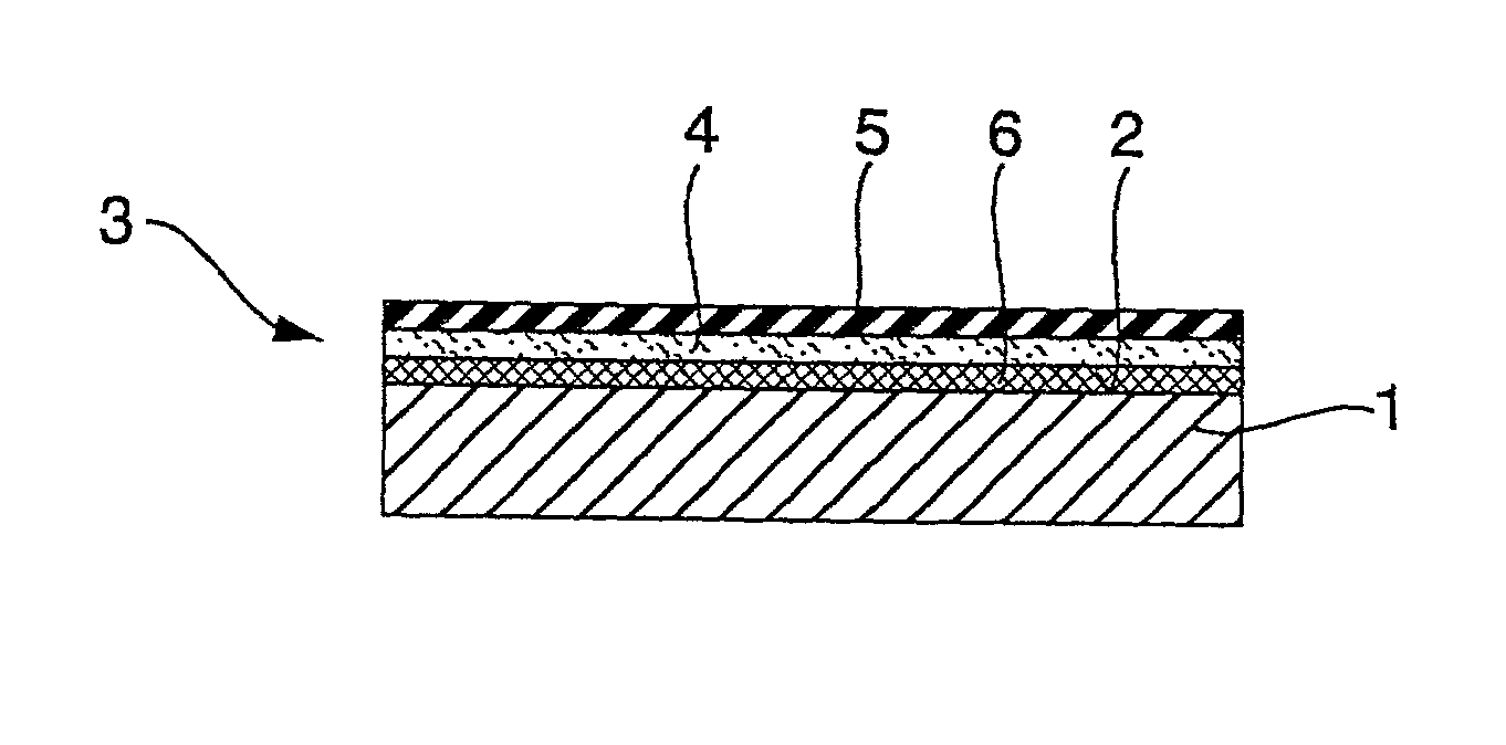
[0024] According to FIG. 3, the protective coating 3 according to the invention in a third embodiment can have, in addition to the sealing coating 4, a component coating 6 formed for example from a crystalline material in the manner of a conventional protective layer. Here the single-layer or multilayer component coating 6 is arranged directly on the surface 2 of the component 1, while the sealing coating 4 is applied to the component coating 6. In this embodiment, the sealing coating 4 protects the component coating 6 and in particular its corrosion-sensitive and / or oxidation sensitive and / or erosion sensitive grain boundaries from a direct attack by the aggressive media. The life of the crystalline component coating 6, and thus the life of the component 1, are hereby increased.


PUM

PropertyMeasurementUnit
Thicknessaaaaaaaaaa
Corrosion propertiesaaaaaaaaaa

Abstract

The invention relates to a sealing coating for a thermally stressed component, particularly a turbine component, for protection from corrosion and/or oxidation and/or erosion. To improve the life of the protective coating or of the component, the protective coating has a single-layer or multilayer sealing coating of an amorphous material.

Description

[0001] The invention relates to a protective coating for a thermally stressed component, particularly a turbine component, for protection against corrosion and / or oxidation and / or erosion.[0002] Turbine components, particularly turbine blades, are exposed to corrosive and / or oxidizing and / or erosive media. The turbine components usually consist of materials which are optimized as regards the mechanical loads which arise in operation of the turbine. These materials, which are for example based on nickel-based alloys, are however relatively susceptible to corrosion, oxidation and / or erosion. Usual basic materials for turbine components, particularly for turbine blades, are: CM 247, CMSX 4, and IN 738.DESCRIPTION OF PRIOR ART[0003] In order to increase the life of turbine components, their corrosion resistance can be improved by the application of a protective coating of the kind mentioned at the beginning. Known protective coatings consist of a metallic, crystalline material, which us...

Claims


Application Information

Patent Timeline
IPC IPC(8): C23C28/00C23C28/04C23C30/00F01D5/28F02C7/00F23M5/00
CPCC23C28/00C23C28/04C23C30/00F01D5/288F23M5/00F23M2900/05001F23M2900/05004F05D2300/228F05D2300/611F05D2300/2118F05D2300/2112Y10T428/12493
Inventor BOSSMANN, HANS-PETERKRANZMANN, AXELREISS, HARALDSCHMUTZLER, HANS JOACHIMSOMMER, MARIANNEWEILER, LUDWIG
Owner ALSTOM (SWITZERLAND) LTD
Why Eureka
Try Eureka