UV reflectors and UV-based light sources having reduced UV radiation leakage incorporating the same

a technology of ultraviolet light and reflector, which is applied in the direction of instruments, discharge tube luminescnet screens, lighting and heating apparatus, etc., can solve the problems of reducing the uniform color and light intensity of the light, and reducing the radiation leakage of ultraviolet ligh

Inactive Publication Date: 2002-12-05
GE LIGHTING SOLUTIONS LLC
View PDF0 Cites 247 Cited by
  • Summary
  • Abstract
  • Description
  • Claims
  • Application Information

AI Technical Summary

Benefits of technology

0008] The present invention also provides UV-based light sources having a uniform color and light intensity and reduced UV radiation leakage. The UV-based light source comprises a LED emitting UV radiation, a shaped structure that comprises a molding or casting material covering the LED, particles of at least one phosphor that is excitable by the UV radiation emitted by the LED and particles of at least one UV-radiation scattering material dispersed substantially uniformly in at least a portion of the molding or casting material. The particles of the phosphor composition and the scattering material are disposed in the vicinity of the LED. The molding or casting material may be a glass or a polymeric material that is substantially transparent after curing. As used herein, a substantially transparent material is defined as one that transmits greater than 80% of incident light having a wavelength of 555 nm at an incident angle of less than 10 degrees.

Problems solved by technology

LED-based lighting devices that use phosphors in a dispersed layer around the LED for light conversion often suffer from the undesirable halo effect and the penumbra effect.
The halo effect occurs because of the poor mixing of light emitted by the phosphor and that by the LED.
However, these patents do not disclose or suggest that dispersants are used in these or similar devices for any benefits other than color mixing or blending or what the desired characteristics of these dispersants are.
However, these patents do not teach the selection of the materials having high and low refractive indices, the design, or the construction of the multilayer LWP filter to achieve these goals.

Method used


Image

  • UV reflectors and UV-based light sources having reduced UV radiation leakage incorporating the same
  • UV reflectors and UV-based light sources having reduced UV radiation leakage incorporating the same
  • UV reflectors and UV-based light sources having reduced UV radiation leakage incorporating the same

Examples


Embodiment Construction

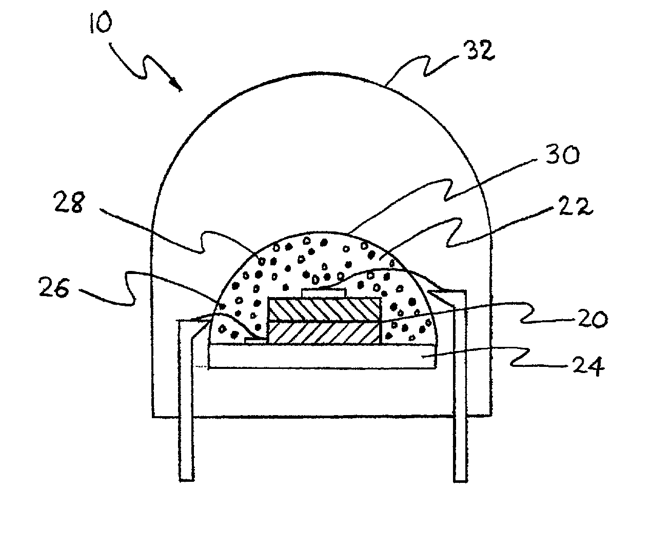
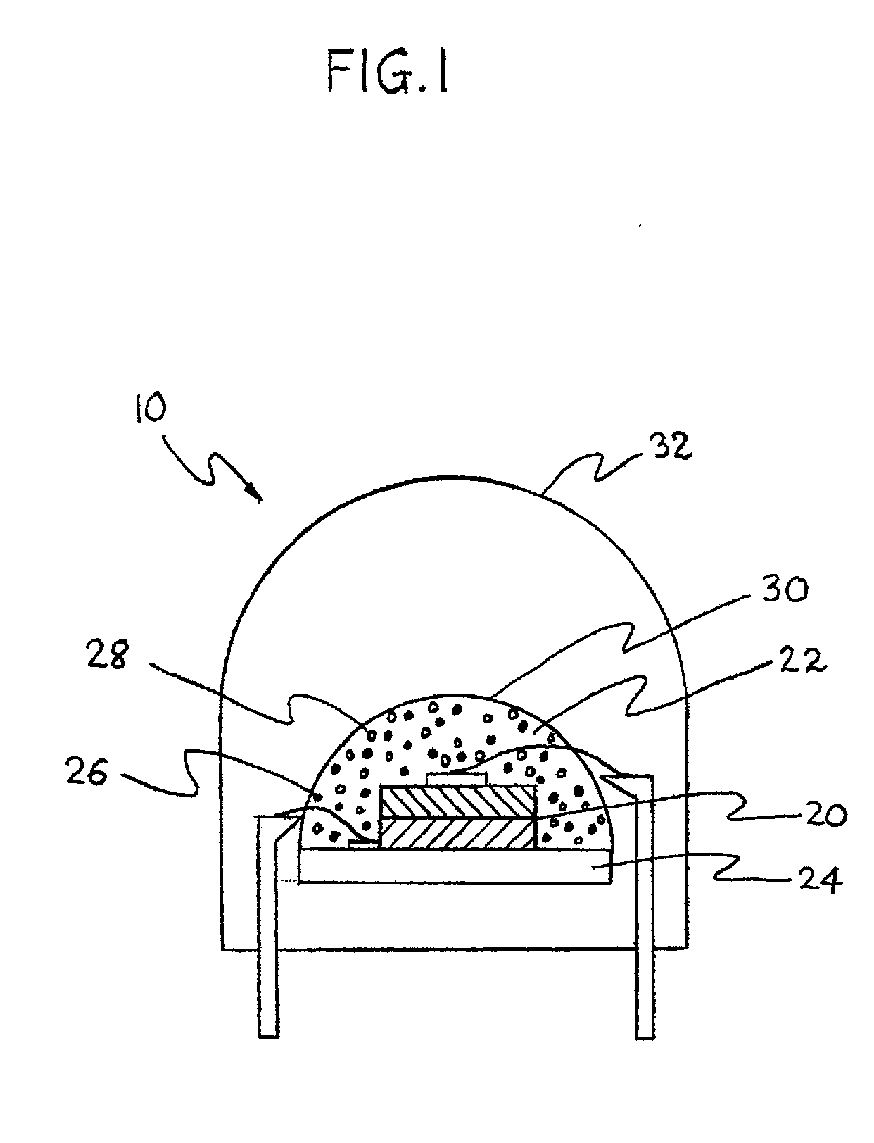
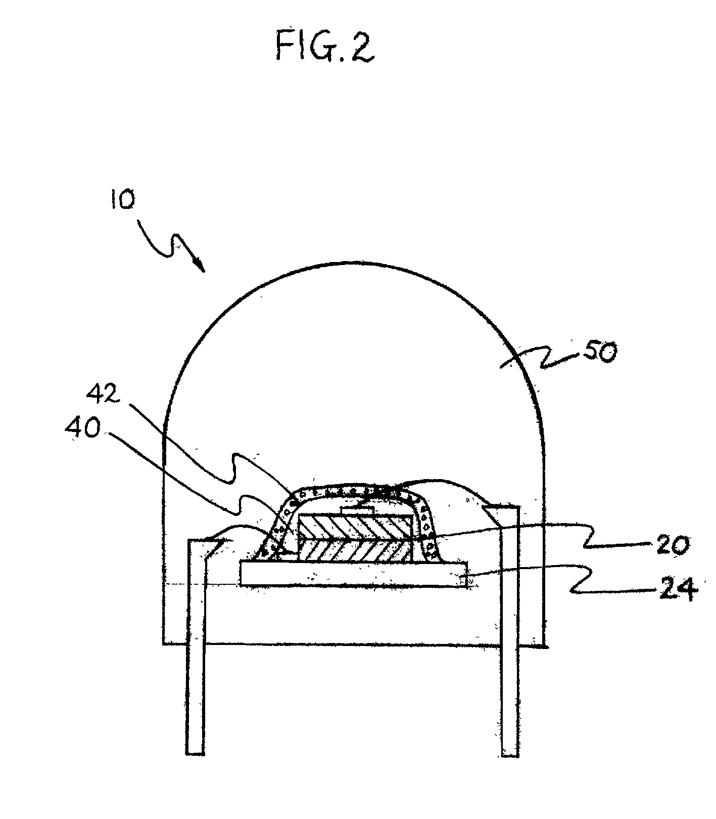
[0021] Visible light sources based on UV LEDs typically comprise a phosphor composition disposed adjacent to a LED to convert the UV radiation to visible light. The phosphors used in the present invention absorb UV radiation energy and reemit light having longer wavelengths, typically in the visible spectrum. The combination of the UV LED and the phosphor is typically enclosed in a substantially transparent shaped structure of a molding or casting material, such as glass, epoxy, silicone, or urea formaldehyde thermoset resin. Alternatively, the phosphor particles are often dispersed in the molding or casting material to provide a better dispersion of light. Typically, the amount of phosphor particles used is small. Therefore, there is a considerable probability for UV light to escape from the light source without being absorbed and converted by the phosphor particles. This unconverted UV radiation not only lowers the light output of the light source but also presents a safety concer...


PUM


Abstract

UV reflectors incorporated in UV LED-based light sources reduce the amount of UV radiation emission into the surroundings and increase the efficiency of such light sources. UV reflectors are made of nanometer-sized particles having a mean particle diameter less than about one-tenth of the wavelength of the UV light emitted by the UV LED, dispersed in a molding or casting material surrounding the LED. Other UV reflectors are series of layers of materials having alternating high and low refractive indices; each layer has a physical thickness of one quarter of the wavelength divided by the refractive index of the material. Nanometer-sized textures formed on a surface of the multilayered reflector further reduce the emission of UV radiation into the surroundings. UV LED-based light sources include such a multilayered reflector disposed on an encapsulating structure of a transparent material around a UV LED, particles of a UV-excitable phosphor dispersed in the transparent material. Alternatively, the transparent material also includes nanometer-sized particles of a UV-radiation scattering material.

Description

BACKGROUND OF THE INVENTION[0001] The present invention relates to ultraviolet ("UV") reflectors and UV-based light sources incorporating the same. More particularly, the present invention relates to visible light sources that are based on semiconductor UV light-emitting devices and have reduced UV emission to the surroundings.[0002] Semiconductor light-emitting diodes and laser diodes (hereinafter collectively called "LEDs") have gained importance as light sources in many applications because of their low power consumption with relatively good luminescence efficiency and of recent advances in manufacturing technology of GaN-based semiconductor devices. Light sources have been disclosed in which radiation or light from UV light- or blue light-emitting LEDs is converted to light having generally longer wavelengths, particularly in the visible range. In the present invention disclosure, the terms "radiation" and "light" are used interchangeably to mean electromagnetic radiation having...

Claims


Application Information

Patent Timeline
Patent Type & Authority Applications(United States)
IPC IPC(8): G02B5/20H01L33/44H01L33/50
CPCB82Y20/00G02B5/206H01L2933/0091H01L33/44H01L33/501G02B5/208H01L2224/48091H01L2224/48247H01L2924/19107
Inventor MCNULTY, THOMAS FRANCISDOXSEE, DANIEL DARCYROSE, JAMES WILSON
Owner GE LIGHTING SOLUTIONS LLC
Why Eureka
Try Eureka