
Method and device for patient temperature control employing optimized rewarming

a patient and temperature control technology, applied in the field of patient temperature control using optimized rewarming, can solve the problems of serious ischemic injury, limited minimum allowable surface temperature, and patient thermoregulation

Inactive Publication Date: 2003-01-30
ZOLL CIRCULATION
View PDF99 Cites 20 Cited by
  • Summary
  • Abstract
  • Description
  • Claims
  • Application Information

AI Technical Summary

Problems solved by technology

One problem with hypothermia as a therapy is that the patient's thermoregulatory defenses initiate, attempting to defeat the hypothermia.
However, the minimum allowable surface temperature is limited by the characteristics of blood.
When the blood approaches freezing, ice emboli may form in the blood, which may lodge downstream, causing serious ischemic injury.
Furthermore, reducing the temperature of the blood also increases its viscosity, which results in a small decrease in the value of the convection heat transfer coefficient.
In addition, increased viscosity of the blood may result in an increase in the pressure drop within the artery, thus compromising the flow of blood to the brain.
The mechanisms by which the value of the convection heat transfer coefficient may be increased are complex.
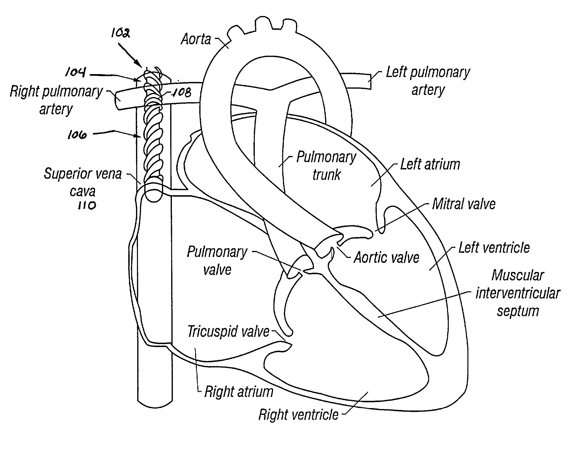
However, the blood flow in the superior vena cava still has a high degree of inherent mixing or turbulence.
However, turbulence in the very thin boundary layer will not produce sufficient kinetic energy to produce the necessary heat transfer rate.
This can create high levels of turbulence intensity in the free stream, thereby sufficiently increasing the heat transfer rate.
For a swirling flow in a tube in which the azimuthal velocity of the fluid vanishes toward the stationary outer boundary, any non-vanishing azimuthal velocity in the interior of the flow will result in an instability in which the inner fluid is spontaneously exchanged with fluid near the wall, analogous to Taylor cells in the purely azimuthal flow between a rotating inner cylinder and stationary outer cylinder.
This instability results from the lack of any force in opposition to the centripetal acceleration of the fluid particles moving along helical paths, the pressure in the tube being a function only of longitudinal position.
Practical constraints limit the value of these parameters and how much they can be manipulated.
Consequently, the value of the surface area S is limited by the physical constraints imposed by the size of the artery into which the device is placed.
Surface features, such as fins, can be used to increase the surface area of the heat transfer element, however, these features alone cannot usually provide enough surface area enhancement to meet the required heat transfer rate.
The allowable surface temperature of the heat transfer element is limited by the characteristics of blood.
When the blood approaches freezing, ice emboli may form in the blood which may lodge downstream, causing serious ischemic injury.
Furthermore, reducing the temperature of the blood also increases its viscosity which results in a small decrease in the value of {overscore (h)}.sub.c.
Increased viscosity of the blood may further result in an increase in the pressure drop within the vessel, thus compromising the flow of blood.
Such mechanisms can create high levels of turbulence intensity in the free stream, thereby increasing the heat transfer rate.
Embodiments of the device use a heat transfer element design that produces a high level of turbulence in the free stream of the blood and in the working fluid.
In all of these embodiments, the design forces a high level of turbulence in the free stream of the blood by causing the blood to navigate a tortuous path while passing through the artery.
This tortuous path causes the blood to undergo violent accelerations resulting in turbulence.
Such obstacles tend to create turbulence in the free stream of blood.
In particular, the form of turbulence is the creation of von Karman vortices in the wake of the flow of blood, downstream of the cylindrical obstacles.
Typical inflatable materials are not highly thermally conductive.
In some patients, the heat transfer element of FIG. 27 may not fit in the internal carotid artery.
Of course, other surface features may also be used which result in turbulence in fluids flowing past them.
A purely tapered (nonsegmented) form may replace the tapered segmental form, but the former may be more difficult to manufacture.
This surface feature may induce turbulence in the working fluid, thereby increasing the convective heat transfer rate in the manner described above.
Such pressures are unlikely to damage the walls of the vessel because of the increased flexibility of the inflated device.
Such drugs minimize the effect of vasoconstriction which may otherwise hinder heat transfer and thus cooling of the patient.
Such drugs also prohibit responses such as shivering which may cause damage to cardiac-compromised patients by increasing their metabolic rate to dangerous levels.
(step 442), shivering and vasoconstriction would deleteriously result.
Of course, it is also known that blankets warmer than about 42.degree. C. can damage patient's skins, this then being an upper limit to the blanket temperature.
Absorption of heat from the blood by the heat exchange region results in cooling of the body.
Meperidine usage has a number of undesirable side effects, and many are related to the affinity for the opiate receptor.
The most serious is respiratory sedation, which can result in death, and may be related to affinity for the delta opiate receptor.
Nor-meperidine is known to have central nervous system toxicity and can cause seizures.
Meperidine cannot be used in patients with renal insufficiency or kidney failure due to a rapid build up of the normeperidine metabolite.
In addition, meperidine cannot be used in patients taking monoamine oxidase inhibitors, due to complications such as convulsions and hyperpyrexia.
However, the mechanisms by which enzyme environmental temperature controls thrombolysis are not yet well characterized.
The activity of .alpha..sub.2-antiplasmin is lessened at low temperatures and thus is less effective at inactivating plasmin.
Pro-UK, like tPA, cannot efficiently activate plasminogen in solution, but it can readily activate plasminogen bound to fibrin.

Method used


Image

  • Method and device for patient temperature control employing optimized rewarming
  • Method and device for patient temperature control employing optimized rewarming
  • Method and device for patient temperature control employing optimized rewarming

Examples


example two (

NON-DRUG)

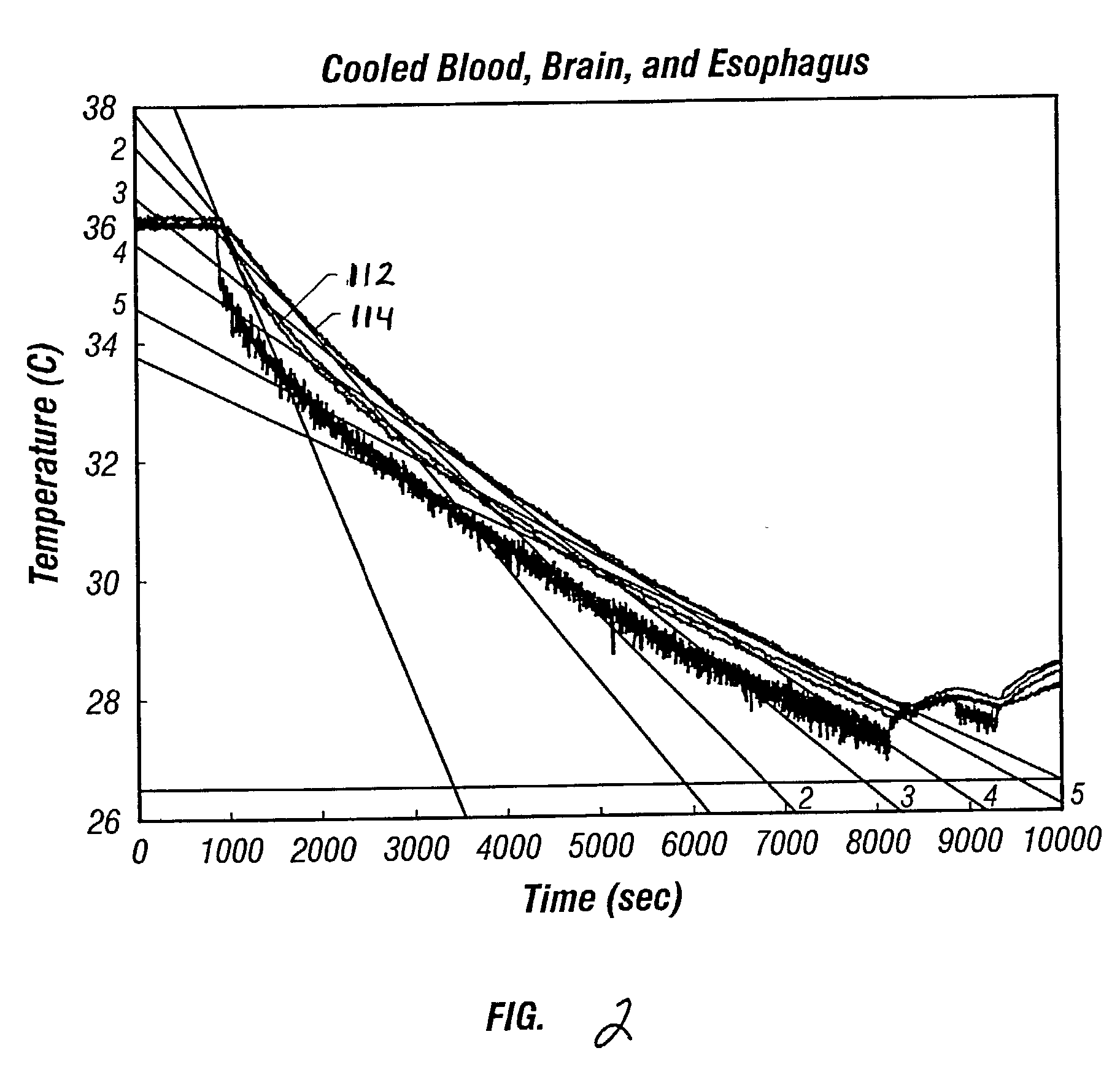
[0369] In another non-drug study of the effect of temperature on fibrinolysis, clot lysis in dogs was investigated while varying clot temperatures in a range of 20.degree. C. to 36.degree. C. The dog's temperature was lowered from a normal temperature to a low temperature. A gradual rewarming period followed the low temperature period.

[0370] Enhanced clot lysis was observed at lower temperatures as compared to higher temperatures. In particular, the maximum fibrinolytic activity occurred in the early rewarming period, i.e., from 20.degree. C. to about 25.degree. C. It is believed that this study can be extended to humans, and that fibrinolytic activity can be enhanced at lower temperatures, especially during periods of rewarming.

[0371] An advantage of all of these embodiments of the method is that clot lysis can be achieved in a simple manner and without the need for drugs. An additional advantage results from the reduced temperature of the blood which helps to protect the ...

example three (

SK)

[0378] Researchers have investigated the effect of temperature on the fibrinolytic activity of an SK mixture. In one such effort, clots were treated with a mixture of plasminogen (2 mg) and SK (100 IU) in a total volume of 15 ml PBS. The temperature of the clots was raised from 24.degree. C. to 37.degree. C. These researchers found that heating enhanced the fibrinolytic activity. In other words, heating from a hypothermic temperature to normal body temperature increased clot lysing for clots treated with SK.

[0379] It is believed that such general trends may be extended to patients without lack of accuracy. Patients may be provided with a drug such as streptokinase and may undergo hypothermia using, e.g., one of the devices or methods described above. In particular, a cooling catheter may be placed in an artery supplying blood to a thrombosed vessel. The catheter may include a separate lumen through which the SK mixture may be delivered. A coolant or working fluid may be supplied ...

example four (

TPA)

[0380] Researchers have also investigated the effect of temperature on the fibrinolytic activity of tPA. Clots were treated with 2.5 .mu.g / ml tPA and incubated at various temperatures (e.g., 37.degree. C., 25.degree. C., 10.degree. C., 0.degree. C., and -8.degree. C.). Plasminogen activation was relatively high at low temperatures (e.g., 0.degree. C. or -8.degree. C.) and was much less at higher temperatures. In other words, these researchers found that, for tPA, cooling to a hypothermic temperature from normal body temperature increased fibrinolytic activity.

[0381] As above, it is believed that such trends may be extended to patients without lack of accuracy. In this case, patients may be provided with tPA and may undergo hypothermia using an above device placed in an artery supplying blood to a thrombosed vessel. The catheter may include a separate lumen through which tPA may be delivered. A coolant or working fluid may be supplied to the cooling catheter, causing the catheter...


PUM


Abstract

Embodiments of the invention provide a system for temperature control of the human body. The system includes an indwelling catheter with a tip-mounted heat transfer element. The catheter is fluidically coupled to a console that provides a heated or cooled heat transfer working fluid to exchange heat with the heat transfer element, thereby heating or cooling blood. The heated or cooled blood then heats or cools the patient's body or a selected portion thereof. In particular, strategies for optimizing the rewarming of patients for various medical procedures are provided, including stroke, neurosurgery, and myocardial infarction.

Description

CONTINUING INFORMATION[0001] This application is a continuation-in-part of U.S. Appl. Ser. No. 09 / 650,940, entitled "SELECTIVE ORGAN HYPOTHERMIA METHOD AND APPARATUS," filed on Aug. 30, 2000; Ser. No. 09 / 785,243, entitled "CIRCULATING FLUID HYPOTHERMIA METHOD AND APPARATUS," filed on Feb. 16, 2001; Ser. No. 09 / 566,531, entitled "METHOD OF MAKING SELECTIVE ORGAN COOLING CATHETER," filed on May 8, 2000; Ser. No. 09 / 757,124, entitled "INFLATABLE CATHETER FOR SELECTIVE ORGAN HEATING AND COOLING AND METHOD OF USING THE SAME," filed on Jan. 8, 2001; Ser. 09 / 714,749, entitled "METHOD FOR LOW TEMPERATURE THROMBOLYSIS AND LOW TEMPERATURE THROMBOLYTIC AGENT WITH SELECTIVE ORGAN TEMPERATURE CONTROL," filed on Nov. 16, 2000; Ser. No. 09 / 621,051, entitled "METHOD AND DEVICE FOR APPLICATIONS OF SELECTIVE ORGAN COOLING," filed on Jul. 21, 2000; Ser. No. 09 / 800,159, entitled "METHOD AND APPARATUS FOR LOCATION AND TEMPERATURE SPECIFIC DRUG ACTION SUCH AS THROMBOLYSIS," filed on Mar. 6, 2001; Ser. No...

Claims


Application Information

Patent Timeline
Patent Type & Authority Applications(United States)
IPC IPC(8): A61F7/00A61F7/02A61F7/12A61M25/00
CPCA61B18/02A61B2017/00292A61B2018/0212A61B2018/0262A61F7/12A61F7/123A61F2007/0056A61F2007/0288A61F2007/126A61M25/00A61M25/0023A61M2025/0004A61M2025/006A61M2205/3606
Inventor MAGERS, MICHAEL
Owner ZOLL CIRCULATION
Learn More