

Surface-coated machining tools
- Summary
- Abstract
- Description
- Claims
- Application Information
AI Technical Summary
Benefits of technology
Problems solved by technology
Method used
Image

Examples
first through thirteenth embodiment examples
[0038] First through Thirteenth Embodiment Examples
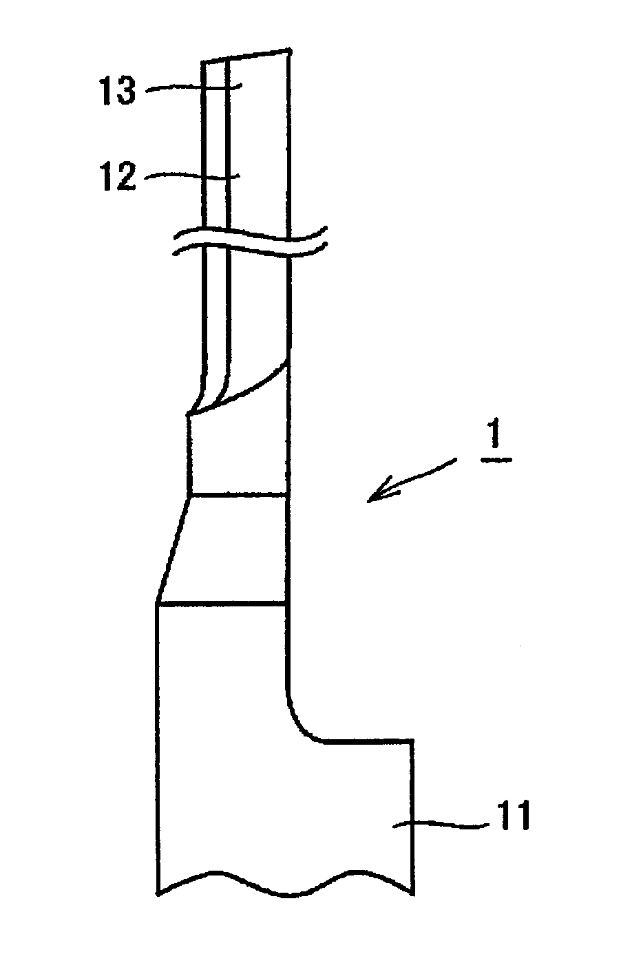
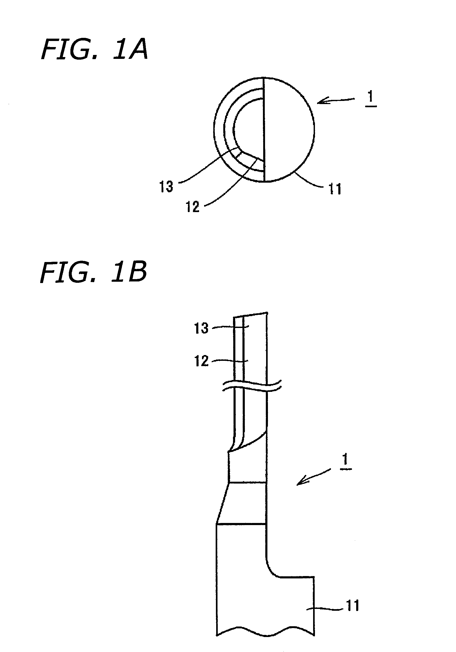
[0039] The surface-coated machining tool in these embodiment examples consists of a router cutter for PCB processing, and is depicted in Figs. 1A and 1B. In the Fig. 1A is a plan view, and 1B is an elevational view.
[0040] As shown in Fig. 1, router cutter 1 has a shank 11 that is clamped in a milling machine chuck, and a blade portion 12.
[0041] As a base material a router cutter, with a blade-portion 12 diameter of 0.8 mm and a blade length of 6 mm, made of a WC-based cemented carbide containing tungsten carbide and cobalt, with the cobalt inclusion amount being 4 weight % or more and 12 weight % or less, was readied. Using a publicly known arc deposition method employing metal vapor-deposition source raw materials and nitrogen gas and / or methane gas to form a compound thin film 13 onto the surface of the base material, surface-coated router cutters 1 for Embodiment Examples 1 through 12, set forth in Table I, were readied.
[0042] Ta...
PUM
| Property | Measurement | Unit |
|---|---|---|
| Grain size | aaaaa | aaaaa |
| Grain size | aaaaa | aaaaa |
| Percent by mass | aaaaa | aaaaa |
Abstract
Description
Claims
Application Information