Coil-embedded dust core and method for manufacturing the same, and coil and method for manufacturing the same

a technology of dust core and coil, which is applied in the direction of transformer/inductance coil/winding/connection, inductance with magnetic core, inductance, etc., can solve the problems of joint failure, prone to failure during compression, and no consideration of connection parts between

Inactive Publication Date: 2003-07-31
TDK CORPARATION
View PDF0 Cites 27 Cited by
  • Summary
  • Abstract
  • Description
  • Claims
  • Application Information

AI Technical Summary

Problems solved by technology

In this case, connection parts are inside the magnetic body, which makes them prone to failures while compressing.
However, no consideration has been given to connection parts between the coil and terminal sections, and joint failures (including poor joining) are likely to occur due to the fact that joining is difficult since it takes place between the magnetic body section and an electrode at the interface with the core.
Here again, part of the terminal that forms a connection part with the coil is inside the core, which makes it prone to failures in the connection parts during the process to form a unitary structure.
Failures are likely to occur in the connection parts in this case as well.
Namely, the coil-embedded dust core or the inductor in Japanese Patent-Laid-Open Nos. 5-291046 and 11-273980, and Japanese Patent No. 2958807 has a coil and terminal sections embedded within magnetic powder, which makes it prone to joint failures between the coil and the terminal sections or insulation failures of the coil and the terminal sections with respect to the magnetic powder.
When a joint failure or an insulation failure occurs, it is difficult to determine the cause of the failure and in many cases takes a long time, since the coil and the terminal sections form connection parts inside the magnetic powder.
Furthermore, the inductor described in Japanese Patent No. 3108931 entails a high possibility for a joint failure to occur in connection parts between a coil and terminal sections after molding, du

Method used


Image

  • Coil-embedded dust core and method for manufacturing the same, and coil and method for manufacturing the same
  • Coil-embedded dust core and method for manufacturing the same, and coil and method for manufacturing the same
  • Coil-embedded dust core and method for manufacturing the same, and coil and method for manufacturing the same

Examples


Embodiment Construction

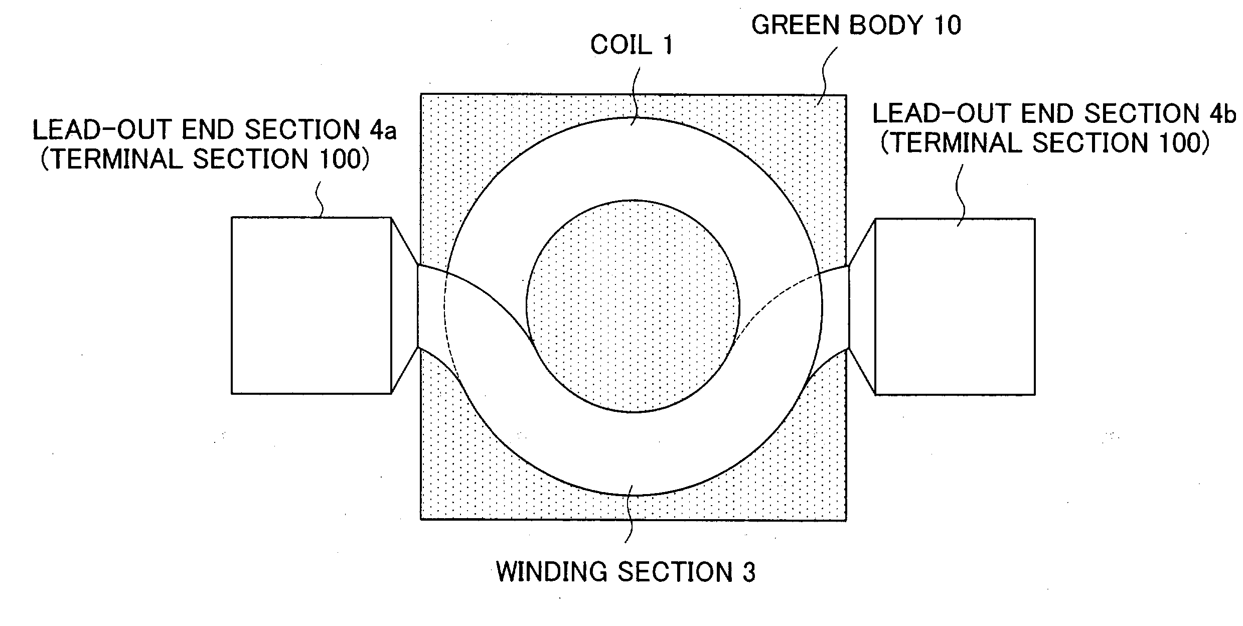
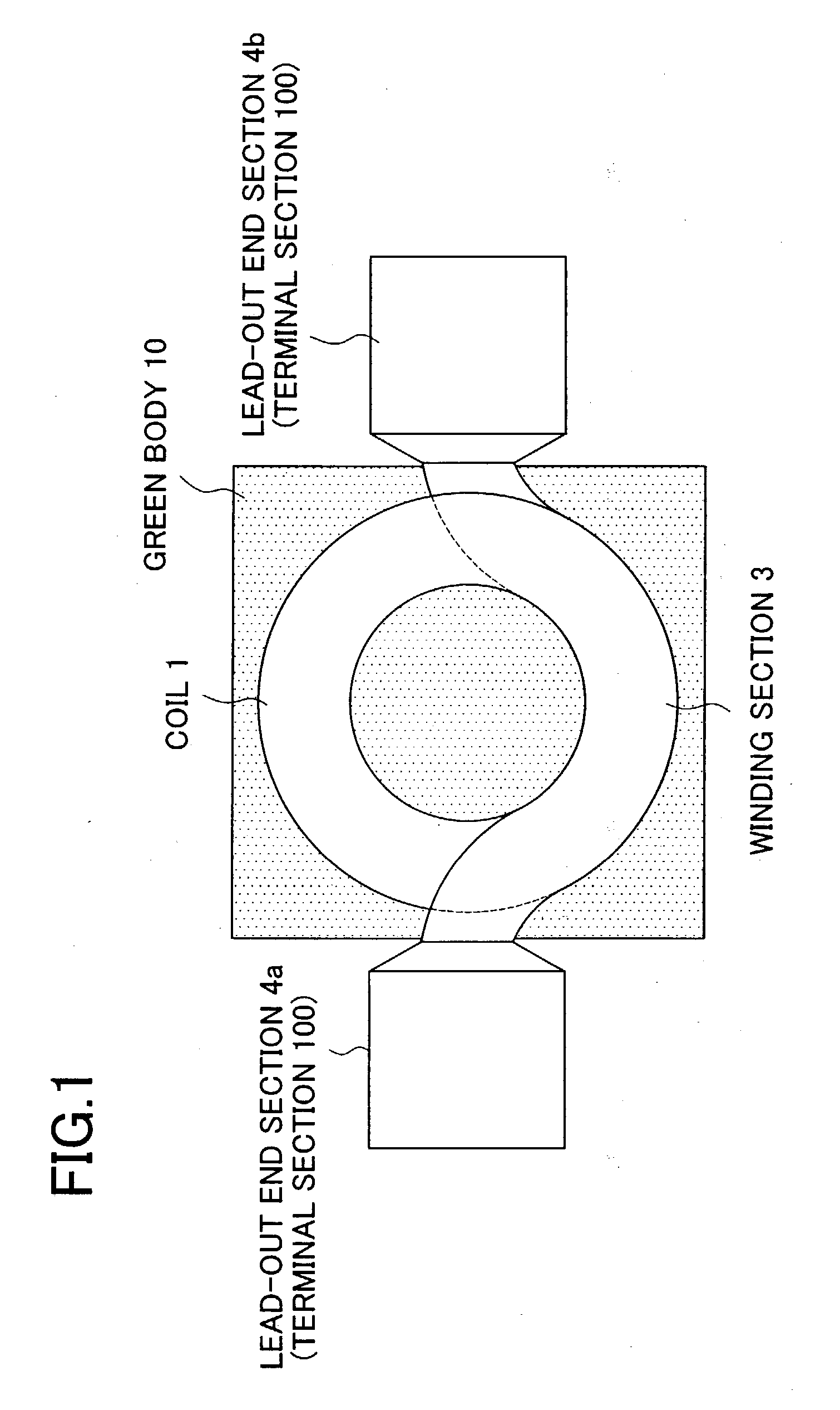
[0106] The coil-embedded dust core in accordance with the present invention will be described in detail by using an example.

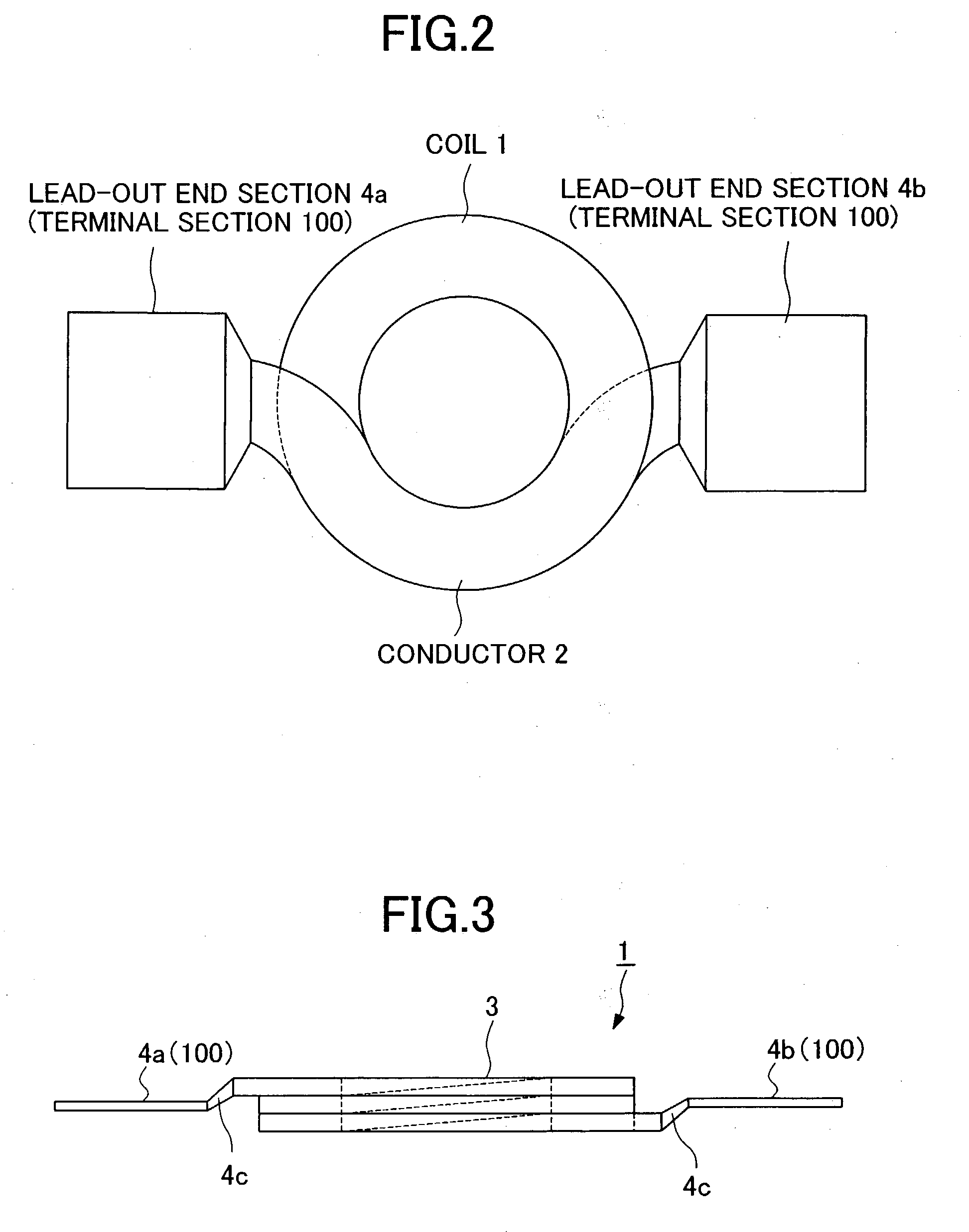
[0107] An experiment conducted to ascertain the inductance value of the coil-embedded dust core in the case where the coil 1 in which the lead-out end sections 4a and 4b are formed on the same plane by bending and the coil 200 in which the lead-out end sections 4a and 4b are not formed on the same plane are used is explained as the example. Both of the coil 1 and the coil 200 are formed by winding the conductor 2 2.5 turns.

[0108] Twenty samples of the coil-embedded dust core were made according to the following procedure:

[0109] The following were prepared:

[0110] Magnetic powder: Permalloy powder manufactured through atomizing method (45% Ni--Fe; mean particle size 25 .mu.m)

[0111] Insulating material: silicone resin (SR2414LV by Toray Dow Corning Silicone Co., Ltd.)

[0112] Cross-linking agent: organic titanate (TBT B-4 by NIPPON SODA CO., LTD.)

[0113] Lubricant: a...


PUM


Abstract

There are provided a coil-embedded dust core that provides high inductance and a method for manufacturing the same. The coil-embedded dust core includes a coil 1 formed by winding a flat conductor 2 and a green body 10 comprising of ferromagnetic metal powder coated with an insulating material. The coil 1 is composed of a winding section 3 in which the flat conductor 2 having front and back surfaces opposed to each other with a predetermined distance is wound and lead-out end sections 4a and 4b that are extended from the winding section 3. Either one of the front and back surfaces of the lead-out end section 4a and either one of the front and back surfaces of the lead-out end section 4b are formed so as to be on the same plane. By using the coil 1 in which the both end sections (lead-out end sections 4a and 4b) are formed on the same plane, the coil-embedded dust core can be made smaller in size, and high inductance can be provided.

Description

[0001] 1. Field of the Invention[0002] The present invention relates to a coil-embedded dust core, which may be used in inductors having a unitary structure with a magnetic core and in other electronic components. The present invention also relates to a method for manufacturing the coil-embedded dust core.[0003] 2. Description of the Related Art[0004] In recent years, electric and electronic equipment has become more compact, and dust cores that are compact (low in height) yet able to accommodate large current have come to be in demand.[0005] Materials used for dust cores are ferrite powder and ferromagnetic metal powder, but ferromagnetic metal powder has larger saturation magnetic flux density than ferrite powder and its DC bias characteristics may be maintained even in a strong magnetic field. Consequently, in making a dust core that can accommodate large current, using ferromagnetic metal powder as a material for dust core has become mainstream.[0006] In addition, in order to fu...

Claims


Application Information

Patent Timeline
IPC IPC(8): H01F17/04H01F1/22H01F27/02H01F27/255H01F27/28H01F27/29H01F41/02H01F41/04
CPCH01F27/022H01F27/027H01F27/255H01F2017/046H01F27/29H01F41/0246H01F41/04H01F27/2847
Inventor MORO, HIDEHARUSUZUKI, TSUNEO
Owner TDK CORPARATION
Why Eureka
Try Eureka