Semiconductor flip-chip package and method for the fabrication thereof

a technology of semiconductors and flip-chips, applied in the direction of semiconductor/solid-state device details, soldering apparatus, manufacturing tools, etc., can solve the problems of inability to meet the requirements of the substrate, failure, and poor reliability of the solder joints, and achieve the effect of disassembly from the substra

Inactive Publication Date: 2003-11-27
INVENSAS CORP
View PDF4 Cites 36 Cited by
  • Summary
  • Abstract
  • Description
  • Claims
  • Application Information

AI Technical Summary

Benefits of technology

0026] In another aspect of the present invention, the chip / first portion of encapsulant / discrete solder bump assembly described above is coated with a thin layer of the second portion of the encapsulant which is either lightly filled or completely devoid of filler material. Placement of the chip, solder reflow and adhesive cure follows as described above.
0027] In another aspect of the present invention, there is provided a method for placing a flip-chip onto a substrate that avoids entrapment of gas bubbles or creation of voids. The chip, having the first portion of encapsulant thereon, is oriented at an angle to the substrate having the second portion thereon, then pivoted about the first point of contact until the solder bumps on the chip are in contact with the solder pads on the substrate, creating an underfill of encapsulant material as the chip is pivoted while expelling the gas from between the chip and substrate.
0028] Another aspect of the present invention provides a chip with underfilling encapsulant pre-coated and pre-assembled on the chip for assembly to a substrate, wherein the encapsulant consists of more than one layer, each layer performing one or more distinct functions such as attachment, stress distribution, electrical redistribution, reworkability, adhesion, or other functions. The bulk of the encapsulant, consisting of one or more layers, is applied and partially or fully hardened prior to assembly of the chip on the substrate. Holes therein which expose metallized contact pads on the active surface of the chip are subsequently filled with solder or an electrically conductive adhesive as previously described to create an encapsulated subassembly. Then a flux adhesive is applied between the chip / encapsulant / solder bump combination and the substrate which can be fully hardened after or when the chip / encapsulant / solder bump combination is placed on the substrate and the solder is reflowed.
0029] Removal of the chip from the substrate is made possible by incorporating in the pre-coated multi-layer encapsulant a polymer layer that can be remelted even after the chip has been assembled to the substrate. Remelting the solder and the polymer encapsulant layer allows removal of the chip for repair or replacement after assembly or for test and burn-in of the chip prior to final assembly. Thus the chip can be disassembled from the substrate without damage to either chip or substrate.
0030] In another aspect of the present invention there is provided a redistribution of the chip's electrical interconnection pads by incorporating in the pre-coated multilayer encapsulant an electrical redistribution layer comprising a thin printed circuit layer with electrical circuitry thereon. The interconnect pads on the chip are attached by solder bumps, conductive adhesive or wire bonds to the redistribution layer. The redistribution layer is subsequently encapsulated. Holes in the encapsulant expose metallized contact pads on the active surface of the redistribution layer. The holes are subsequently filled with solder as previously described. Then a flux adhesive layer is applied between the chip / encapsulant / redistribution layer subassembly and the substrate. The flux adhesive is applied remaining unhardened until the subassembly is placed on the substrate and the solder is reflowed.
0031] Another aspect of the present invention also provides within the precoated encapsulant a novel compliant flexible structure wherein the solder and encapsulant expand or contract laterally without cracking or delaminating upon heating or cooling of the chip and substrate. The novel encapsulant mainly provides the adhesive mechanical bond required to hold the chip on the substrate while the solder mainly provides the electrical interconnection required between the chip and the substrate.

Problems solved by technology

One obstacle to flip-chip technology when applied to polymer printed circuits is the unacceptably poor reliability of the solder joints due to the mismatch of the coefficients of thermal expansion between the chip, having a coefficient of thermal expansion of about 3 ppm / .degree. C., and the polymer substrate, e.g. epoxy-glass having a coefficient of thermal expansion of about 16 to 26 ppm / .degree. C., which causes stress build up in the solder joints.
Because the structural solder joints are small, they are thus subject to failures.
The underfill process, however, makes the assembly of encapsulated flip-chip printed wire boards (PWB) a time consuming, labor intensive and expensive process with a number of uncertainties.
After reflow, due to the close proximity of the chip to the substrate, removing flux residues from under the chip is such a difficult operation that it is generally not done.
These residues are known to reduce the reliability and integrity of the encapsulant.

Method used


Image

  • Semiconductor flip-chip package and method for the fabrication thereof
  • Semiconductor flip-chip package and method for the fabrication thereof
  • Semiconductor flip-chip package and method for the fabrication thereof

Examples


example 2

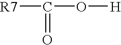
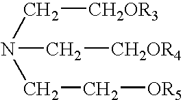
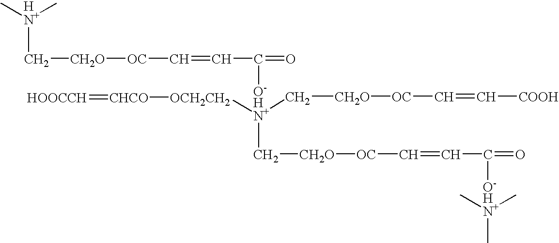
[0139] Preparation of tris (maleic acid) triethanolamine monoester: an amine fluxing agent, with the structure: 6

[0140] Three moles of maleic anhydride (294 grams) were heated in a flask at 80.degree. C. until fully melted at which time one mole of triethanolamine (149 grams) was slowly added thereto over the course of one hour, so that gelation did not occur. The composition was constantly stirred and maintained at 80.degree. C. To ensure that the reaction went to completion, the product was maintained at 80.degree. C. with constant stirring for an additional hour. The reactants were kept in a nitrogen atmosphere throughout. Then the product was allowed to cool to room temperature. Monitoring the reaction on a Fourier-transform infrared spectrometer, the OH vibrational band at 3,400-3,500 cm.sup.-1 of the triethanolamine was observed to become minimized while an ester vibration band at 1,710-1,740 cm.sup.-1 appeared and maximized, indicating complete reaction of the triethanolamine...

example 3

[0142] Preparation of methyl meso-erythritol tetramaleic acid monoester:

[0143] 39 g maleic anhydride was heated to 80.degree. C. until all the maleic anhydride was melted before 12.2 g of meso-erythritol was added under mechanical stirring. The temperature was then raised to 130.degree. C. for 30 minutes followed by cooling down to 80-90.degree. C. for 2 hours. The reaction is: 7

example 4

[0144] Preparation of pentaerythritol ethoxylate tetramaleic acid monoester:

[0145] 39 g maleic anhydride was heated to 80.degree. C. until all the maleic anhydride was melted before 27 g pentaerythritol ethoxylate (average Mn ca 270) was added under mechanical stirring. The reactants are stirred at 80.degree. C. for 2-3 hours to complete the reaction. The reaction is: 8


PUM

PropertyMeasurementUnit
Tgaaaaaaaaaa
temperatureaaaaaaaaaa
temperaturesaaaaaaaaaa

Abstract

A simplified process for flip-chip attachment of a chip to a substrate is provided by precoating the chip with an encapsulant underfill material having separate discrete solder columns therein to eliminate the conventional capillary flow underfill process. Such a structure permits incorporation of remeltable layers for rework, test, or repair. It also allows incorporation of electrical redistribution layers. In one aspect, the chip and pre-coated encapsulant are placed at an angle to the substrate and brought into contact with the pre-coated substrate, then the chip and pre-coated encapsulant are pivoted about the first point of contact, expelling any gas therebetween until the solder bumps on the chip are fully in contact with the substrate. There is also provided a flip-chip configuration having a complaint solder/flexible encapsulant understructure that deforms generally laterally with the substrate as the substrate undergoes expansion or contraction. With this configuration, the complaint solder/flexible encapsulant understructure absorbs the strain caused by the difference in the thermal coefficients of expansion between the chip and the substrate without bending the chip and substrate.

Description

[0001] This application claims the benefit of U.S. Provisional Application Nos. 60 / 053,407, filed Jul. 21, 1997, and 60 / 056,043, filed Sep. 2, 1997, and incorporates herein the disclosures of those applications in their entirety.FIELD OF THE:INVENTION[0003] This invention relates generally to semiconductor chips electrically and mechanically connected to a substrate, particularly to flip-chip configurations.[0004] Flip-chip technology is well known in the art. A semi-conductor chip having solder bumps formed on the active side of the semi-conductor chip is inverted and bonded to a substrate through the solder bumps by reflowing the solder. Structural solder joints are formed between the semi-conductor chip and the substrate to form the mechanical and electrical connections between the chip and substrate. A narrow gap is left between the semi-conductor chip and the substrate.[0005] One obstacle to flip-chip technology when applied to polymer printed circuits is the unacceptably poor ...

Claims


Application Information

Patent Timeline
Patent Type & Authority Applications(United States)
IPC IPC(8): B23K35/02B23K35/36B32B7/12C09J4/00H01L21/48H01L21/56H01L21/60H01L23/29H01L23/433H01L23/48H01L23/498H05K1/09H05K3/32
CPCB23K35/025B23K35/3613B23K35/3618B32B7/12C09J4/00H01L21/563H01L23/293H01L23/4334H01L23/49827H01L23/49883H01L24/11H01L24/29H01L24/81H01L24/83H01L2224/1147H01L2224/1148H01L2224/13099H01L2224/13111H01L2224/16225H01L2224/274H01L2224/73204H01L2224/8121H01L2224/81815H01L2224/83101H01L2224/83191H01L2224/83192H01L2224/83193H01L2224/83856H01L2924/01004H01L2924/01005H01L2924/01015H01L2924/01018H01L2924/0102H01L2924/01025H01L2924/01027H01L2924/01029H01L2924/0103H01L2924/01039H01L2924/01042H01L2924/01046H01L2924/01047H01L2924/01049H01L2924/0105H01L2924/01051H01L2924/01078H01L2924/01079H01L2924/01082H01L2924/01322H01L2924/01327H01L2924/0781H01L2924/14H01L2924/15311H01L2924/3511H05K1/095H05K3/321H01L2924/0132H01L2224/32225H01L2224/29101H01L2224/29H01L2224/2919H01L2924/01006H01L2924/01023H01L2924/01033H01L2924/01045H01L2924/014H01L2924/0665H01L2924/1579H01L2224/29111H01L2224/81011H01L2224/81024H01L2224/1182H01L2924/00013H01L2224/29299H01L2224/2929H01L2924/10253H01L2224/73104H01L2224/0401H01L2224/06102H01L2224/1403C08F222/1006C08F222/20H01L2924/00H01L2924/01028H01L2924/00012H01L2924/3512H01L2924/00014H01L2224/29099H01L2224/29199H01L2224/02379H01L2224/16105H01L2224/16108H01L2224/27436H01L2224/27602H01L2224/27614H01L2224/27618H01L2224/29082H01L2224/29562H01L2224/2969H01L2924/12042C08F222/104
Inventor CAPOTE, MIGUEL A.ZHOU, ZHIMINGZHU, XIAOQIZHOU, LIGUI
Owner INVENSAS CORP
Why Eureka
Try Eureka