Chromogenic glazing

a chromogenic glazing and chromogenic technology, applied in the field of chromogenic glazing, can solve the problems of affecting the color range of passengers, affecting the natural skin tone of passengers, and affecting the appearance of passengers' skin tone,

Inactive Publication Date: 2003-12-11
SCHOTT AG
View PDF29 Cites 446 Cited by
  • Summary
  • Abstract
  • Description
  • Claims
  • Application Information

AI Technical Summary

Problems solved by technology

For example, some colors, such as deep violet glazing may make the interior colors appear dull and/or strange and cause the skin tones of passengers to appear unnatural.
Certain EC materials, such as those that derive their color principally from tungsten oxide, can typically color to a blue tint and maybe undesirable in some circumstances because their color change fails to meet the neutral/warm criteria.
To meet the desired characteristics, such EC materials must be modified by doping, so that they will color to a more neutral shade, but in doing so the coloration range may be compromised.
Other compromises made in material selection may affect durability because of electrochemical changes in the material.
While some chromogenic devices may be available that change to a more neutral color, they may not conform to the desired transmission range required for the various locations.
However, it is not only the color of the filters, which are combined, but also how deep the coloration is.
The lower layer thickness will result in higher bleach state transmission of the frontal windows, however, it may not have as high a contrast ratio as the other windows.
When the vehicles are parked for long periods of time this can lead to severe battery drainage and cause inconvenience to the user.
Also, for several types of chromogenic devices, particularly for the EC devices the change in transmission set by the user and the accompanied charge consumed by the device tend to increase with increasing temperature.
Thus the chromogenic glass should typically consume low power and hold their transmission when subjected to these temperatures.
Thus for a glazing to be useful, it must meet the colored and transmission levels described above and consume low power.
However in doing so, due to individual seals, busbar areas and play bet...

Method used


Image

  • Chromogenic glazing
  • Chromogenic glazing
  • Chromogenic glazing

Examples


example 2

Fabrication of an Electrochromic Device (Device 4) With Tungsten Oxide Electrochromic Layer and With Vanadium Oxide Intercalating Counterelectrode. These are Small Devices, Thus Prior Deposition of Busbars Such as Silver Frits is Not Required

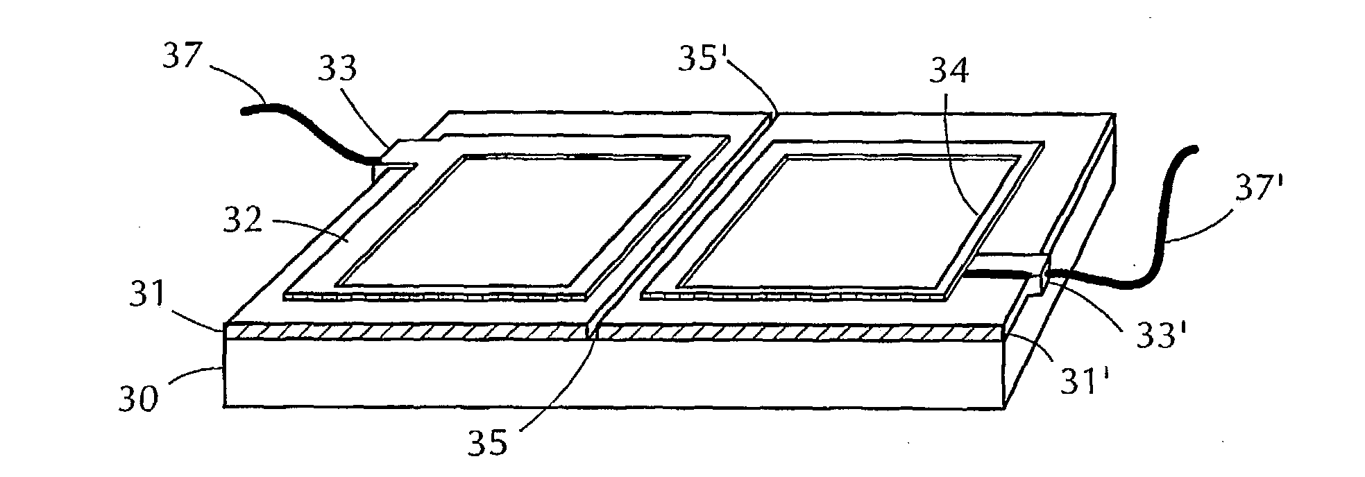
[0117] A 3.times.3 inch (7.6 cm.times.7.6 cm) EC window device (Device 4) was made using TEC 15 (from Pilkington LOF, Toledo, Ohio). The tungsten oxide coating, lithium tungstate (Li.sub.0.3W)O.sub.x, was deposited, as described earlier, on TEC 15 glass. This is not a reduced form of tungsten oxide as lithium is present as an oxide. The thickness of the fired coating was 350 nm. Another piece of similar sized TEC 15 was coated with a vanadium oxide coating (counterelectrode). Both the electrodes in the cell store or intercalate ions. Both electrodes posses electrochromic properties, but the doped tungsten oxide imparts stronger coloration. This substrate had two small holes (about {fraction (1 / 16)} of an inch (1.6 mm)) about 1.5 cm from two of i...

example 3

Preparation of a EC Device (Device 5a,b) Which Uses LiMnNiO Counterelectrode

[0125] A solution to deposit LiMnNiO electrode was prepared as follows. 1.56 g of lithium methoxide was dissolved in 50 ml of distilled ethanol. Separately 9.28 g of Nickel(ll)ethylhexanoate (78% in 2 ethylhexanoic acid) and 18.81 g of manganese(ll)2-ethylhexanoate (40% in mineral spirits) were mixed and stripped off in a rotary evaporator (@90.degree. C.) of about 8.91 g of volatiles. After this 8.91 g of ethanol was added. The two solutions were then mixed together. After they dissolved in each other, a uniform phase was obtained which was used as a coating solution. The substrate (TEC15) was coated by spinning and then fired up to 450.degree. C. under conditions similar to the vanadium oxide described above. The coating thickness was 180 to 200 nm depending on the spinning conditions. A cell (Device 5a) was prepared with tungsten oxide as the other electrode as described above in the case of vanadium oxid...

example 4

Ultrasonic Sealing of Plug Holes

[0126] This is a novel sealing method to close the plug holes (fill ports) which is described in detail in the already filed patent application DE 100 06 199.0. The welding requires a cover or a plug to be placed on top of the plughole or inside the plughole. This cover (or plug) is then bonded on to the glass by fusing its surface with the glass surface. An ultrasonic oscillator rapidly provides the energy required to do this. The equipment employs a press to place the cover with a certain force covering the hole and contacting the substrate, transducers, ultrasonic generator and controller. An equipment supplier for such a system is Telesonic Ultrasonics (Bridgeport, N.J.) who sells such ultrasonic welding systems. The oscillations are typically rotational or translational with respect to the surface normal. In case of the present EC device the holes are plugged by covering them with thin foils or plates. These foils could be made out of a single ma...


PUM

PropertyMeasurementUnit
Lengthaaaaaaaaaa
Fractionaaaaaaaaaa
Angleaaaaaaaaaa

Abstract

A transparent chromogenic assembly in which color changes are selectively effectable over predefined areas comprises a pair of facing transparent substrates (15, 21, 28) each covered with a conductive layer divided into individual energizeable areas each provided with a set of busbars (187, 188). A passive layer may be superimposed over one of the substrates, its color being chosen so that the color and the transmissivity of the passive layer accommodates the range of color change and transmissivity of the electrochromic layer to maintain the transmitted color of the panel in a warm or neutral shade. Various other chromogenic windows, devices and systems are also disclosed.

Description

[0001] 1. Field of the Invention[0002] This invention relates to glazing and, more particularly, to chromogenic glazing for use in applications, such as automobiles and display filters, where it is desirable to reversibly alter the transmission or tinting of the glass. This invention may also be used for other means of transportation glazing such as trucks, buses, boats, planes, trains, etc. and also in building glazing.[0003] 2. RELATED BACKGROUND ART[0004] Automobile windshields, movable and fixed side and rear windows, and divider panels between the front and the rear cabin, as well as sunroofs, employ various forms of glazing in a variety of colors and intensities. Typically, when tinted glazing is employed, the windshield and the front side windows are clear for safety reasons. Car glazing may provide for management of both ultra-violet and infra-red solar energy penetration to enhance user comfort while reducing the power requirements for air-conditioning. Besides the need to ...

Claims


Application Information

Patent Timeline
IPC IPC(8): G02F1/1524G02F1/153G02F1/155G02F1/157G02F1/161G02F1/163
CPCB32B17/10036B32B17/10174G02F1/1521G02F1/1523G02F1/1525G02F2001/1555G02F1/155G02F1/157G02F1/161G02F1/163G02F1/153G02F1/1503G02F1/1524B32B17/10513
Inventor AGRAWAL, ANOOPHANSEN, STEPHANTONAZZI, JUAN CARLOS LOPEZZHANG, RAYMOND
Owner SCHOTT AG
Why Eureka
Try Eureka