Information recording medium, information recording method, and information reproducing method

a technology of information recording and recording mark, which is applied in the field of information recording medium, information recording method, and information reproducing method, can solve the problems of disturbing the recording density from being improved, the required laser power is large, and the end edges of the recording mark are easy to shift, and achieve the effect of high density recording

Inactive Publication Date: 2004-02-12
HITACHI LTD +1
View PDF2 Cites 59 Cited by
  • Summary
  • Abstract
  • Description
  • Claims
  • Application Information

AI Technical Summary

Benefits of technology

0031] The experiment, which gave an embodiment of the present invention, was conducted using a standard optical head receiving the light beam from the substrate side, though using a focusing lens with about 0

Problems solved by technology

To record information on the optical disk, photo-assist magnetic disk, and thermal-assist magnetic disk at a high density, a binary recording or multi-level recording method, namely a modulation system where the lengths of recording marks finely adjusted, has been developed and enables high density recording in theory, though practically, it has such a problem that the start and end edges of the recording mark is easy to shift due to various factors, disturbing the recording density from being improved.
Although it is preferable that the magnetic dis

Method used


Image

  • Information recording medium, information recording method, and information reproducing method
  • Information recording medium, information recording method, and information reproducing method
  • Information recording medium, information recording method, and information reproducing method

Examples


embodiment 1

[0039] Embodiment 1

[0040] (Configuration and Manufacturing Method)

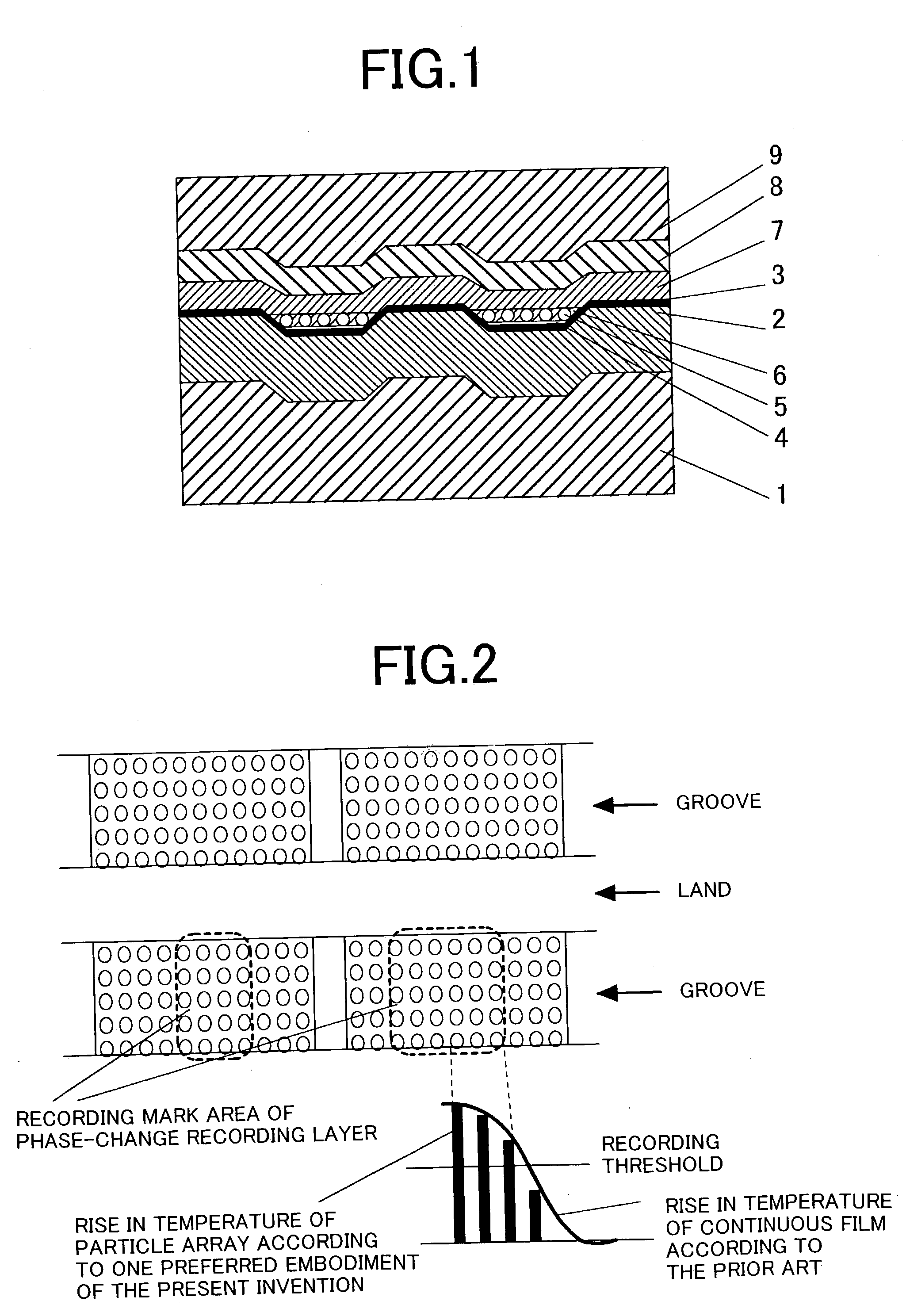
[0041] The recording medium of the present invention has a configuration as shown in FIG. 1.

[0042] This medium was made as described below.

[0043] First, a lower protective layer 2 made from (ZnS).sub.80(SiO.sub.2)-.sub.20 was formed as a 50 nm thick film on a polycarbonate substrate 1 with 8 cm of diameter and 0.6 mm of thickness, of which surface had tracking grooves (width 0.15 .mu.m) with 0.4 .mu.m of track pitch and 25 nm of depth for in-groove recording (land recording from the viewpoint of a optical spot) and, on which addresses were represented by wobble of the grooves.

[0044] Further, on the protective layer, a Ge.sub.2Sb.sub.2Te.sub.5 phase-change recording film 3 with 10 nm of thickness was formed.

[0045] Groove patterns were transcribed on the substrate surface using a nickel master whose groove patterns were transcribed from glass master photo resist.

[0046] As described in the paper on the manufacturing meth...

embodiment 2

[0132] Embodiment 2

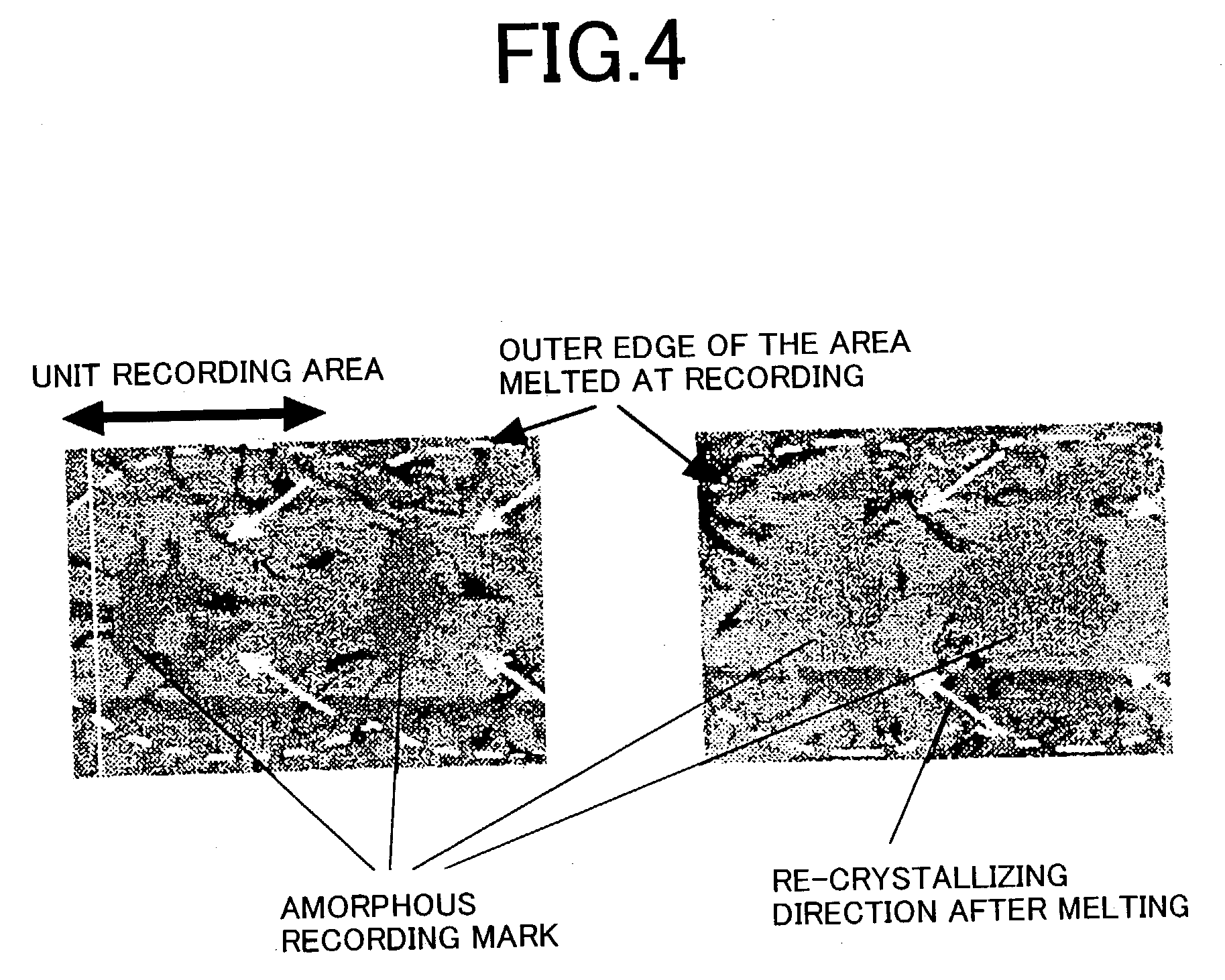
[0133] The recording medium and device configuration according to the second preferred embodiment of the present invention are similar to those according to the first preferred embodiment of the present invention with an exception that multi-level recording was used for the recording system. To achieve multi-level recording, the rate of the space occupied by the recorded mark of the unit length on the recording track was changed.

[0134] If information was multi-level recorded on the standard phase-change recording medium, distortion developed unavoidably in the shape of the recorded mark as shown in FIG. 4 through FIG. 8 in the paper by M. Horie et al., PCOS2001 Proceedings, 2001, p. 20 and subsequent pages and an error tended to occur in read out signals. According to the preferred embodiment of the present invention, for the self assembled recording medium, correct shapes of marks could be recorded when information was recorded in the same manner and correct 4-va...

embodiment 3

[0136] Embodiment 3

[0137] The third preferred embodiment of the present invention relates to a multi-layer recording medium and a recording device, on which information is recorded in / reproduced from the multi-layer recording medium.

[0138] As shown in FIG. 6, the first layer of the recording medium is formed in the same manner as that for the first preferred embodiment of the present invention.

[0139] Note that since the wavelength of the light source used in our experiment is long, wider track pitch (1 .mu.m) and groove width (0.3 .mu.m) were used. Instead of metal particles, SiO.sub.2 particles, around which 5 nm film of cyanine dye was coated and then oleic acid was applied on them, were used.

[0140] In this case, no Ge--Sb--Te recording layer was formed. First, a 10 nm-thick Ag.sub.95Pd.sub.3Cu.sub.2 half transparent reflective layer 11 was formed on the substrate surface for auto-focus and tracking.

[0141] FIG. 6 shows the area from the recording layer to the upper protective laye...


PUM

PropertyMeasurementUnit
Electric energyaaaaaaaaaa
Thicknessaaaaaaaaaa
Magnetic fieldaaaaaaaaaa

Abstract

The information recording medium accosting to the preferred embodiment of the present invention achieves high-speed, high-density recording. The layer, in which ultra-particles made from an optical absorption metal, dielectric, or recording material are formed into regular arrays, is deposited. Resonant Plasmon excitation and resonance absorption of ultra-particles enable the edges of the recorded marks to be identified clearly and intense absorption to occur only in the given layer depending on the wavelength in the case of the multi-layer medium, achieving high-density, large-capacity recording.

Description

BACKROUND OF THE INVENTION[0001] 1. Field of the Invention[0002] The present invention relates to an information recording medium using light, a method for recording information on the information recording medium, and an information recording device.[0003] 2. Description of Related Art[0004] Various principles for recording information by irradiating light on a recording film have been known and among them, those using a change in atomic arrangement caused by heating, for example, phase change in a film material (also referred to as phase transition or phase transformation) have such an advantage that an information recording medium, on which information can be overwritten plural times, is achieved.[0005] For example, as disclosed in JP-A No. 344807 / 2001, this type of phase-change optical disks are composed of a protective layer, a recording film made from a GeSbTe derivative, another protective layer, and reflective layer deposited on a substrate.[0006] On the other hand, optical ...

Claims


Application Information

Patent Timeline
IPC IPC(8): B32B3/02B41M5/26G11B7/00G11B7/0045G11B7/007G11B7/24G11B7/24033G11B7/24035G11B7/24038G11B7/24041G11B7/24088G11B7/243G11B7/244G11B11/10G11B11/105
CPCB82Y10/00Y10T428/25G11B5/02G11B5/64G11B5/66G11B5/82G11B7/00454G11B7/0079G11B7/122G11B7/24G11B7/24038G11B7/24085G11B7/24088G11B7/2585G11B7/259G11B7/26G11B11/10528G11B11/10584G11B11/10586G11B2005/0002G11B2005/0021G11B2007/24308G11B2007/2431G11B2007/24312G11B2007/24314G11B2007/24316Y10T428/21B82Y30/00
Inventor TERAO, MOTOYASUTSUCHIYA, YUKOMATSUMOTO, TAKUYAKOJIMA, KYOKO
Owner HITACHI LTD
Why Eureka
Try Eureka