Eureka AIR delivers breakthrough ideas for toughest innovation challenges, trusted by R&D personnel around the world.

Olefin production utilizing whole crude oil and mild catalytic cracking

a technology of whole crude oil and olefin production, which is applied in the direction of thermal non-catalytic cracking, organic chemistry, chemistry apparatus and processes, etc., can solve the problems of substantial and expensive processing of the starting feedstock of the conventional olefin production plant, as described abov

Inactive Publication Date: 2004-03-18
EQUSR CHEM LP
View PDF4 Cites 172 Cited by
  • Summary
  • Abstract
  • Description
  • Claims
  • Application Information

AI Technical Summary

Benefits of technology

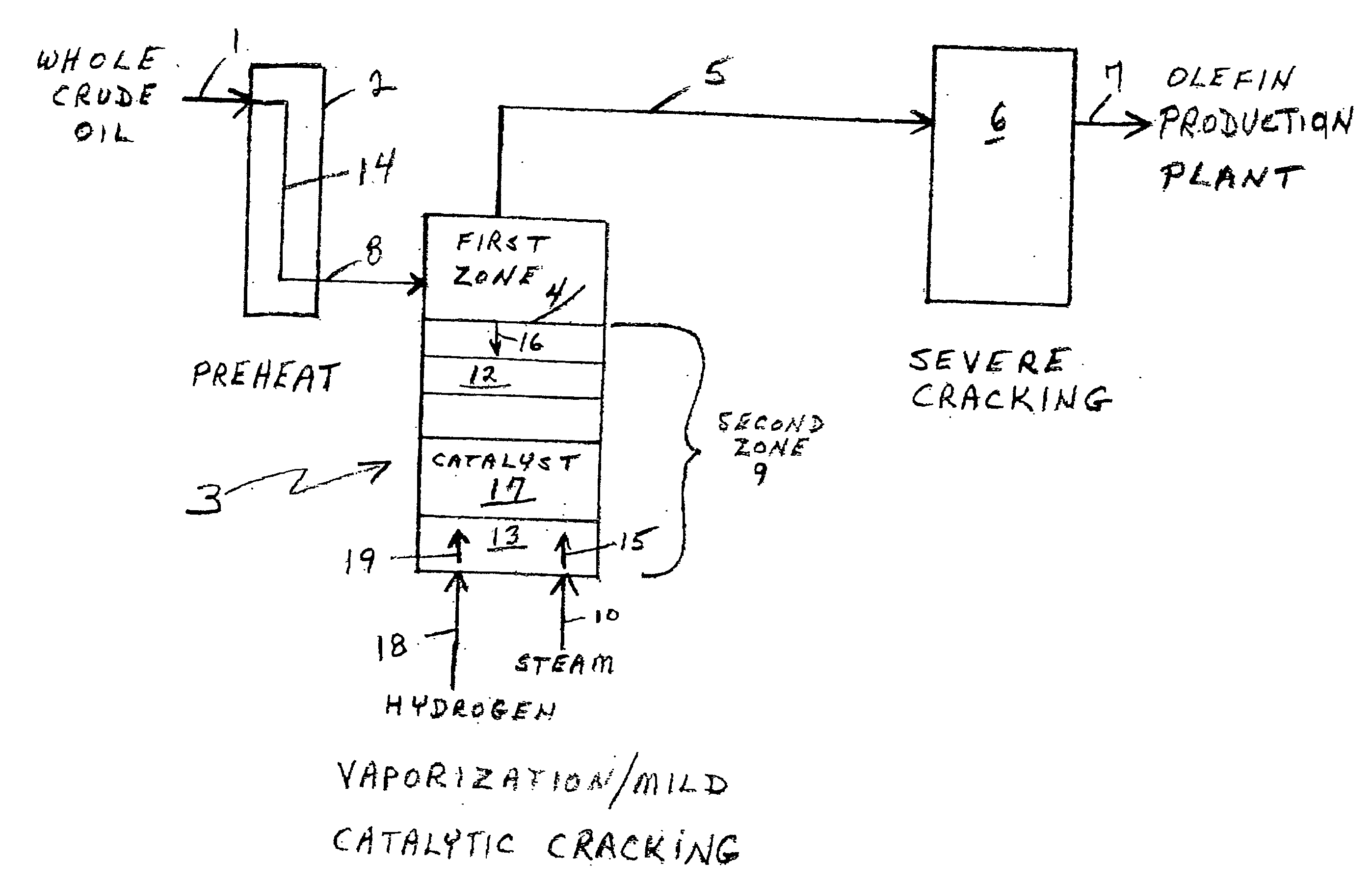
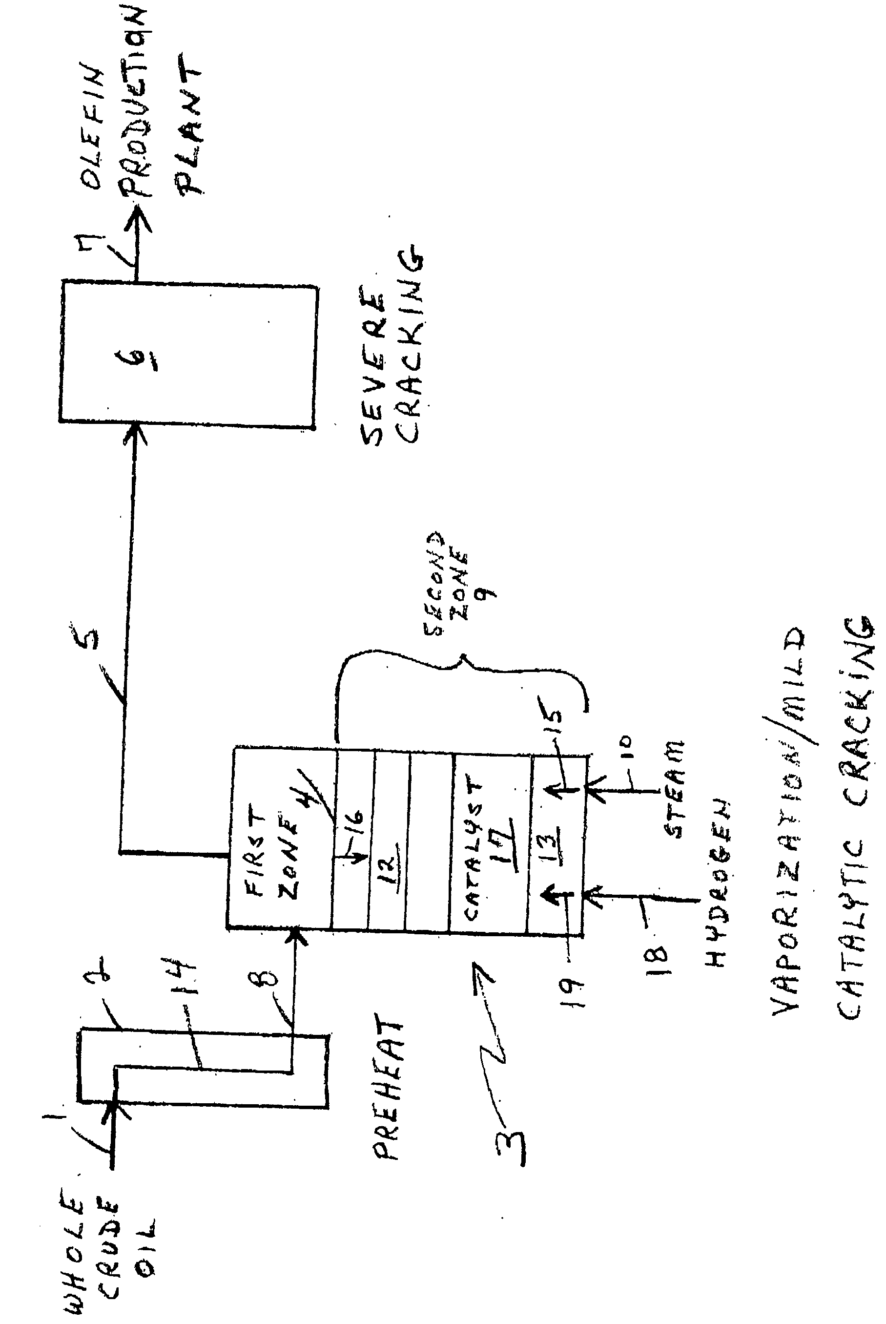
[0034] The special vaporization / mild catalytic cracking operation of this invention receives the whole crude oil primary feed that has been preheated, for example, to from about 500.degree. F. to about 750.degree. F., preferably from about 550.degree. F. to about 650.degree. F. This is a lower temperature range for preheated primary feed than is normally the case for primary feed that exits the preheat section of a conventional cracker and is part of the novel features of this invention. This lower preheat temperature range helps avoid fouling and coke production in the preheat section when operated in accordance with this invention. Such preheating preferably, though not necessarily, takes place in the convection section of the same furnace for which such whole crude is the primary feed. The first zone in this special vaporization / mild catalytic cracking operation is entrainment separation wherein vaporous hydrocarbons and other gases in the preheated stream are separated from those components that remain liquid after preheating. The aforesaid gases are removed from the vaporization / mild cracking section and passed on to the radiant section of the furnace.
[0037] This second zone carries in all or a portion thereof, e.g., a central portion, one or more mildly acidic (Hammett acidity number Ho of about -3 or greater, e.g., -2, -1, etc.) catalysts that facilitate vaporization of the liquid hydrocarbon droplets that are moving through this zone. The catalyst(s) can also remove metal, e.g., vanadium, nickel, iron and the like, from the liquid droplets and retain such metals thereby removing them as a potential problem in subsequent processes employed downstream of the cracking (pyrolysis) furnace. The catalyst(s) employed in this invention, therefore, in addition to a mild acidity, preferably have a surface area of about 80 or greater square meters / gram, a pore volume of at least about 0.28 cubic centimeters / gram, and otherwise provide good mass transfer between vapor, e.g., steam, and the liquid hydrocarbon droplets. The catalyst used also preferably has a low coking tendency.
[0039] The amount of catalyst or catalysts employed will vary widely because crude oil compositions vary widely. Therefore an exact amount or range of amounts is impossible to quantify. However, the amount of catalyst employed will be an effective catalytic amount to at least one of enhance (increase) the vaporization of the hydrocarbon that remains liquid and promotes (facilitates) mild cracking of at least a portion of such liquid hydrocarbon.
[0042] As the liquid hydrocarbon droplets fall, they are vaporized by the high energy steam. This enables the droplets that are more difficult to vaporize to continue to fall and be subjected to higher and higher steam to oil (liquid hydrocarbon) ratios and temperatures to enable them to be vaporized by both the energy of the steam and the decreased liquid hydrocarbon partial pressure with increased steam partial pressure (steam dilution). In addition, the steam may also provide energy for mild thermal and catalytic cracking to reduce the molecular weight of various materials in the droplets thereby enabling them to be vaporized. For certain light whole crude oils used as primary feed in this invention, essentially only vaporization occurs with little, if any, mild catalytic cracking. However, with other heavier whole crude oils the heavier hydrocarbon components therein resist vaporization and move in their liquid state toward the hot steam entering the unit until they encounter sufficiently hot steam and / or sufficient steam dilution to cause mild catalytic cracking of at least a part thereof which mild catalytic cracking is then followed by vaporization of the lighter molecular weight products of the mild catalytic cracking.

Problems solved by technology

The starting feedstock for a conventional olefin production plant, as described above, has been subjected to substantial, expensive processing before it reaches said plant.
However, the prior art teaches away from even hydrocarbon cuts (fractions) that have too broad a boiling range distribution.

Method used


Image

  • Olefin production utilizing whole crude oil and mild catalytic cracking
  • Olefin production utilizing whole crude oil and mild catalytic cracking

Examples


Embodiment Construction

[0059] A whole, straight run crude oil stream from a refinery storage tank characterized as Saharan Blend is fed directly into a convection section of a pyrolysis furnace at ambient conditions of temperature and pressure. In this convection section this whole crude oil primary feed is preheated to about 650.degree. F. and then passed into a separate mild catalytic cracking section wherein gases are separated from liquids, and the gases removed from the mild cracking zone to a radiant section of the same furnace for severe cracking in a temperature range of 1,450.degree. F. to 1,550.degree. F.

[0060] The liquid, after separation from accompanying gases, is retained in the mild catalytic cracking section and allowed to fall downwardly in that section toward the bottom thereof into a catalyst bed composed of activated alumina. Steam at 1,300.degree. F. is introduced into the bottom of zone 9 to give a steam to hydrocarbon ratio at line 5 in the drawing of 1.2 / 1. Hydrogen is introduced a...


PUM

PropertyMeasurementUnit
temperatureaaaaaaaaaa

Abstract

A method for utilizing whole crude oil as a feedstock for the pyrolysis furnace of an olefin production plant wherein the feedstock after preheating is subjected to mild catalytic cracking conditions until substantially vaporized, the vapors from the mild catalytic cracking being subjected to severe cracking in the radiant section of the furnace.

Description

[0001] 1. Field of the Invention[0002] This invention relates to the formation of olefins by thermal cracking of whole crude oil. More particularly, this invention relates to utilizing whole crude oil as a feedstock for an olefin production plant that employs a hydrocarbon cracking process such as steam cracking in a pyrolysis furnace.[0003] 2. Description of the Prior Art[0004] Thermal cracking of hydrocarbons is a petrochemical process that is widely used to produce olefins such as ethylene, propylene, butenes, butadiene, and aromatics such as benzene, toluene, and xylenes.[0005] Basically, a hydrocarbon feedstock such as naphtha, gas oil or other fractions of whole crude oil that are produced by distilling or otherwise fractionating whole crude oil, is mixed with steam which serves as a diluent to keep the hydrocarbon molecules separated. The steam / hydrocarbon mixture is preheated to from about 900.degree. F. to about 1,000.degree. F., then enters the reaction zone where it is ve...

Claims


Application Information

Patent Timeline
Patent Type & Authority Applications(United States)
IPC IPC(8): C10G9/36C10G11/20
CPCC10G11/20C10G9/36
Inventor POWERS, DONALD H.
Owner EQUSR CHEM LP
Why Eureka
Eureka Blog
Learn More