Method for producing a biomimetic membrane, biomimetic membrane and its applications

a biomimetic membrane and biomimetic membrane technology, applied in the direction of fluid speed measurement, optical light guide, photomechanical treatment, etc., can solve the problems of unstable lipid bi-layers, difficult to handle, formation of pores,

Inactive Publication Date: 2004-08-05
COMMISSARIAT A LENERGIE ATOMIQUE ET AUX ENERGIES ALTERNATIVES
View PDF6 Cites 19 Cited by
  • Summary
  • Abstract
  • Description
  • Claims
  • Application Information

AI Technical Summary

Problems solved by technology

Furthermore, lipidic bi-layers have the drawback of being unstable and being not very easy to handle.
However, the very limited number of publications in this field bears witness to the difficulties posed in producing said membranes.
Apart from the fact that the process developed by these Authors requires--as they themselves recognise--carrying out numerous complementary studies before its use can be envisaged on an industrial scale, it turns out that it has the major disadvantage of leading to the formation of a pore in which the wall is necessarily formed of the same material as that which forms the remainder of the membrane.
Furthermore, the feedback loop that makes it possible to control the diameter of the pore o...

Method used


Image

  • Method for producing a biomimetic membrane, biomimetic membrane and its applications
  • Method for producing a biomimetic membrane, biomimetic membrane and its applications
  • Method for producing a biomimetic membrane, biomimetic membrane and its applications

Examples


first embodiment

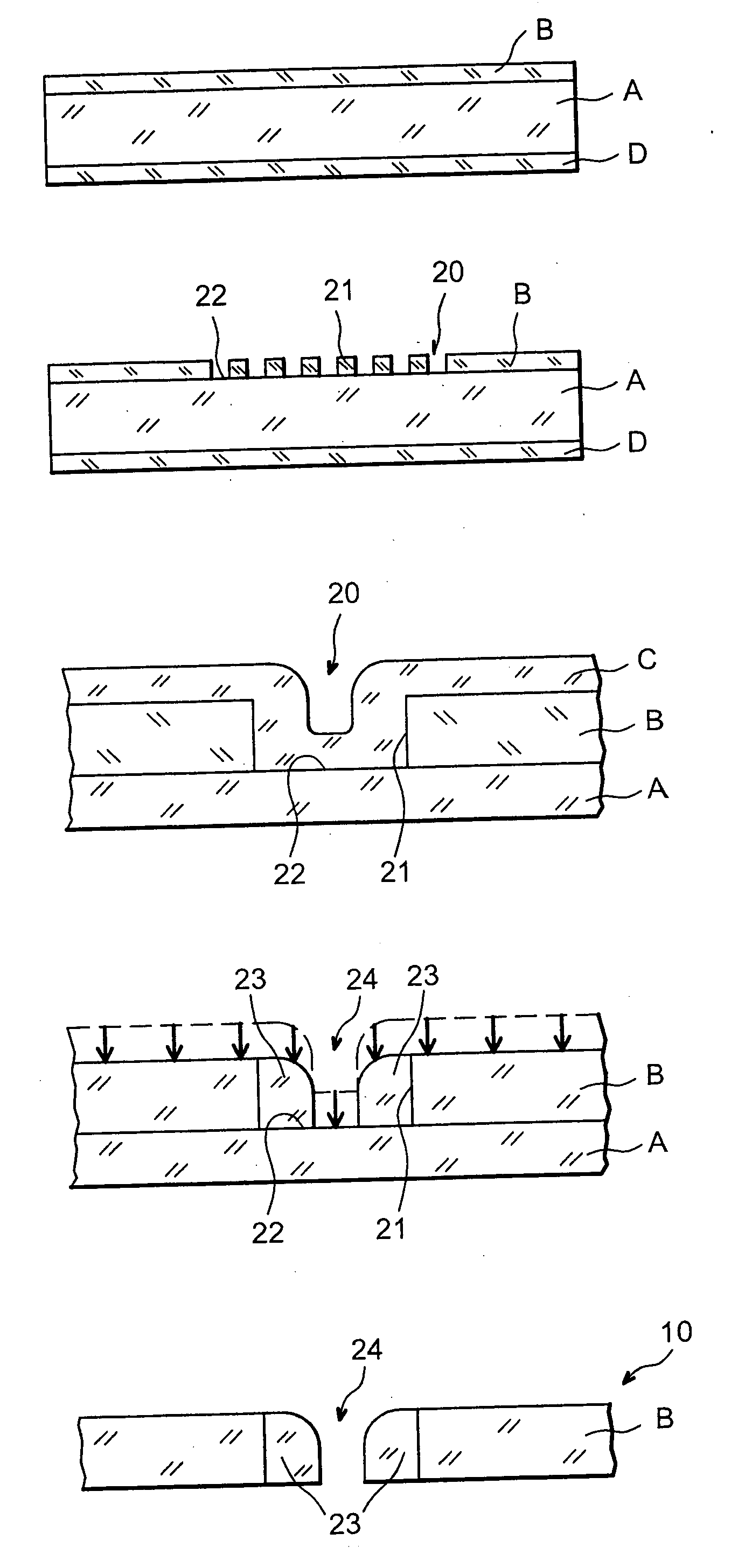
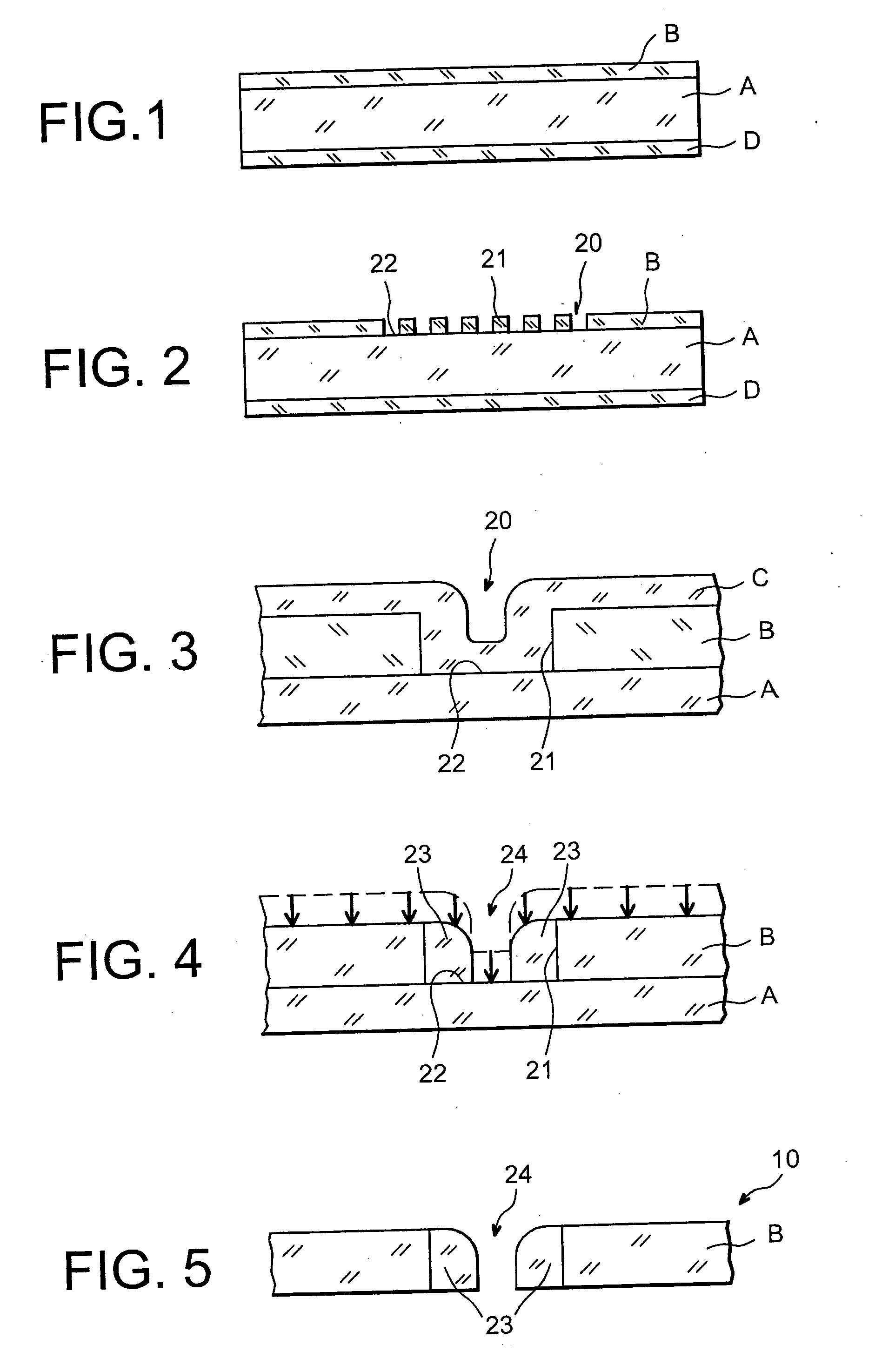
[0121] FIGS. 1 to 5 schematically illustrate, in cross-sectional form, the respective steps a) to e) of the method according to the invention, in said method.

second embodiment

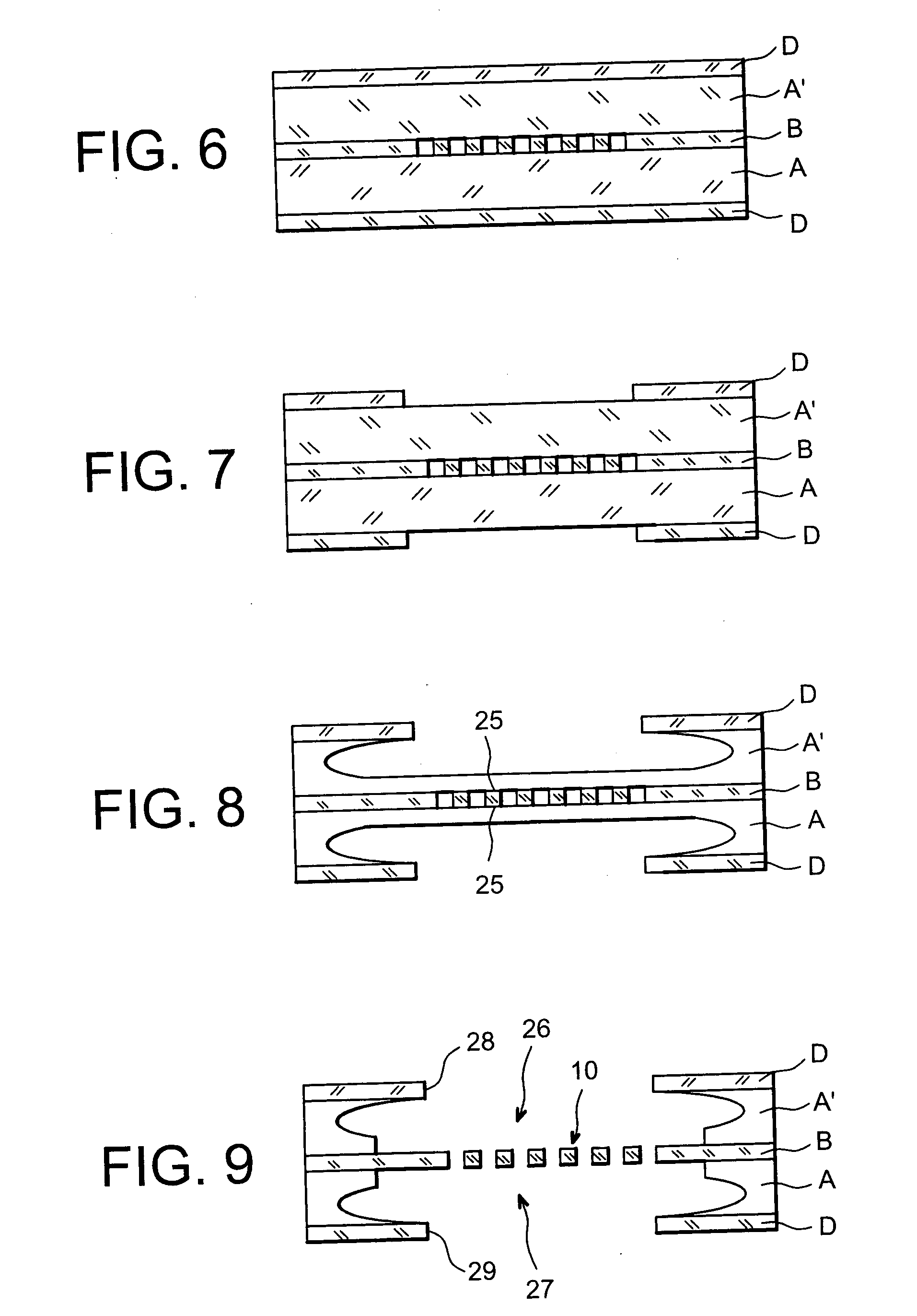
[0122] FIGS. 6 to 9 schematically illustrate, in cross-sectional form, step e) of the method according to the invention in said method.

[0123] FIG. 10 corresponds to two photographs taken with an optical microscope, at two different enlargements (1000.times. and 200.times.), of a membrane as obtained at the end of step e) of the method according to the invention.

[0124] We will refer firstly to FIGS. 1 to 4 which schematically represent the respective steps a) to e) of the method according to the invention, in a first embodiment of said method.

[0125] As can be seen in FIG. 1, the first step of the method, or step a), comprises depositing, on the two principal faces of a plate A formed for example of silicon, two layers, respectively, B and D, formed for example of thermal silicon oxide.

[0126] The second step of the method, or step b), which is illustrated in FIG. 2, consists in forming within layer B, by a lithography followed by a dry etching of said layer, for example by fluorinated...

third embodiment

[0139] FIG. 10 shows two photographs taken with an optical microscope of a membrane as obtained at the end of step e) of the method according to the invention in said method in which layer B has been partially liberated from plate A by dry isotropic etching of said plate by means of a plasma (in a "downstream" or "after-glow" type reactor and in a fluorinated chemistry in the presence of oxygen), said isotropic etching having been carried out through the pores formed in said layer B.

[0140] Part A of FIG. 10 corresponds to a 1000.times.enlargement, whereas part B of said Figure corresponds to a 200.times.enlargement.

[0141] Said membrane has a surface area of around 10 mm.sup.2, a thickness of 100 nm and pores of 350 nm diameter separated from each other by 700 nm.

[0142] Said membrane has been formed by using a plate A in silicon and layers B and C in silicon oxide.

[0143] Part A of FIG. 10 makes it possible to distinguish the matrix of pores of the membrane, whereas part B of said fig...


PUM


Abstract

The invention concerns a method for producing a biomimetic membrane, a biomimetic membrane and the applications of said membrane. Said biomimetic membrane (10) has one or several through pores (24) and is characterised in that it is formed of at least two different micro-machinable materials one of which forms the wall (23) of said pore(s), whereas the other or others of said materials form(s) the remainder of said membrane. Applications: performing studies on the dynamic and functional properties of biological membranes; manufacture of biocatalysis microsystems and detection or dosing of substances.

Description

[0001] The present invention concerns a method for producing a biomimetic membrane, a biomimetic membrane and the applications of said membrane.[0002] More precisely, said method makes it possible to produce a stable porous membrane, the structure of which mimics the structural characteristics of biological membranes and which, moreover, has zones provided with specific physical / chemical properties, in the image of biological membranes.[0003] Said type of membrane is capable of serving as an experimental model in all research work concerning the dynamic and functional properties of biological membranes, and especially for studying the mechanisms of the trans-membrane transport of molecules and the membrane potential, diffusion, reaction and interaction processes at biological interfaces, the functional dynamic of isolated membrane proteins, membrane ligand / receptor recognition and affinity reactions or even the construction of macromolecular architectures on biological interfaces, s...

Claims


Application Information

Patent Timeline
IPC IPC(8): B82B1/00A61L2/00B01D67/00B01D69/02B01D69/06B01D71/02B01J19/00B05D5/00B81B1/00B82B3/00G03F7/00
CPCB01D63/088B01D67/0062B81C1/00158B81B2203/0353B81B2203/0127
Inventor FUCHS, ALEXANDRAHEITZMANN, MICHELVINET, FRANCOISE
Owner COMMISSARIAT A LENERGIE ATOMIQUE ET AUX ENERGIES ALTERNATIVES
Why Eureka
Try Eureka