
Inductive detection for mass spectrometry

a mass spectrometry and inductive detection technology, applied in the direction of electron/ion optical arrangement, particle separator tube details, separation process, etc., can solve the problem of low overall efficiency of current mass spectrometers, unrealized quantitative analysis potential of biological samples, and low overall efficiency

Active Publication Date: 2004-09-02
WISCONSIN ALUMNI RES FOUND
View PDF61 Cites 70 Cited by
  • Summary
  • Abstract
  • Description
  • Claims
  • Application Information

AI Technical Summary

Benefits of technology

[0018] The present invention provides methods, devices and device components using inductive detection for the analysis and detection of electrically charged particles. Particularly well-suited for the time-of-flight analysis of gas phase ions generated from high molecular weight compounds, the detection sensitivity of the electrically charged particle analyzers of the present invention is independent of ion velocity, composition and structure. The methods of time-of-flight analysis of the present invention provide substantial improvements in mass resolution, absolute mass accuracy, mass analysis efficiency and detection efficiency over mass analyzers of the prior art. In addition, the present invention includes methods, devices and device components providing diverse applications of electrically charged particle detection in coincidence, such as ion pre-selection and screening, coordinated acceleration--time-of-flight analysis and methods of molecular sorting.
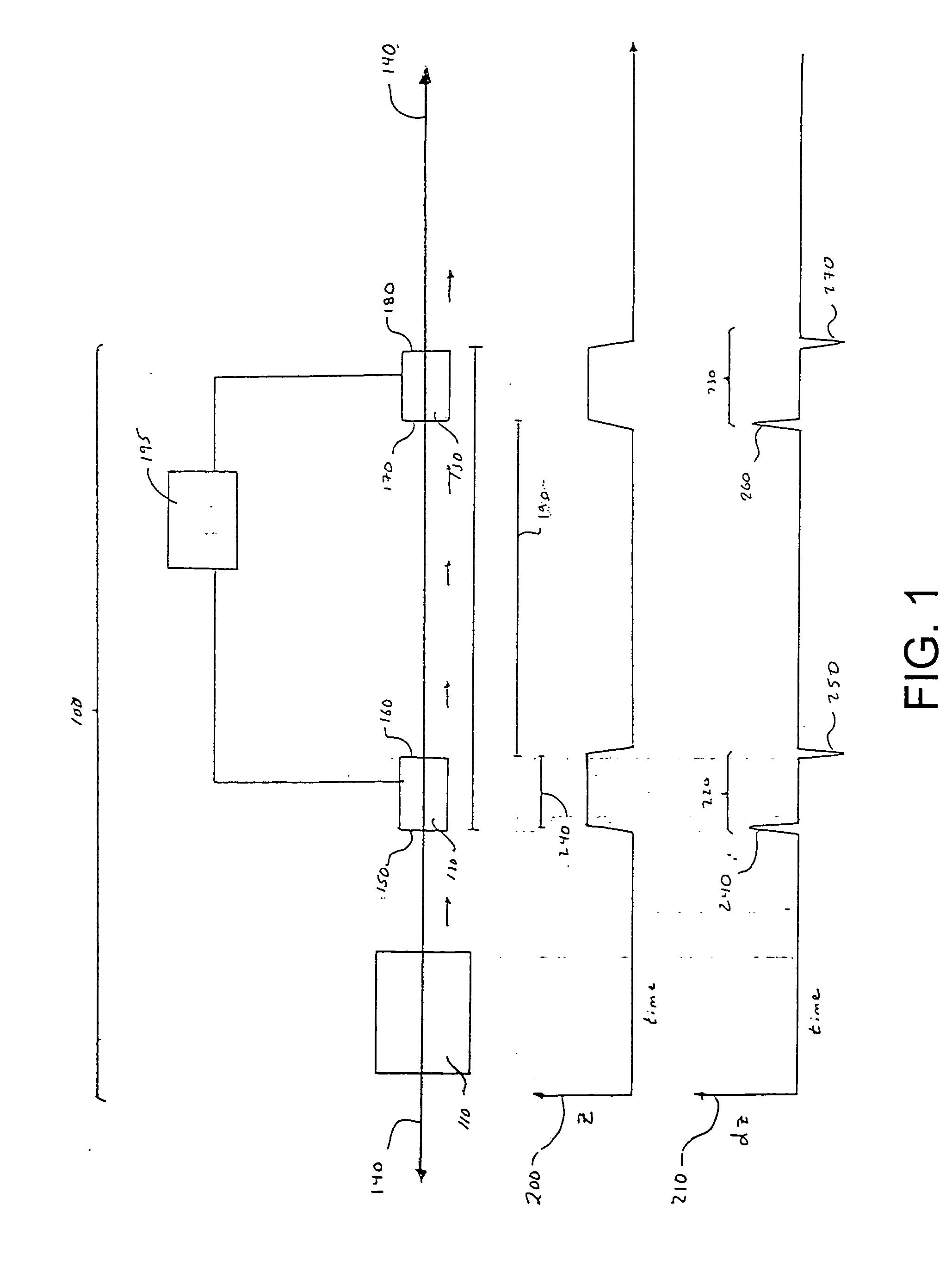
[0019] The present invention comprises methods, devices and device components for analyzing the velocity of electrically charged particles, wherein charged particles translating substantially uniform, well-defined trajectories are conducted through an analysis and detection region having a plurality of charged particle detectors, at least one of which is a non-destructive inductive detector. In an exemplary embodiment, a spatially collimated beam of electrically charged particles or packets of electrically charged particles having momenta substantially directed along an electrically charged particle detection axis is conducted by a first inductive detector, through a selected charged particle flight path and is detected by a second charged particle detector. The first inductive detector is positioned close enough to the electrically charged particle detection axis such that the electric field associated with an electrically charged particle or packet of electrically charged particles induces electric charges on the detector surface, thereby generating a first detection signal at a first detection time. Upon passing by the first inductive detector, electrically charged particles of the spatially collimated beam translate through a selected flight path are detected by a second electrically charged particle detector. The second detector is positioned a selected distance downstream of the first inductive detector along the electrically charged particle detection axis. In a preferred embodiment, the second detector is also an inductive detector positioned close enough to the electrically charged particle detection axis such that the electric field associated with an electrically charged particle or packet of electrically charged particles induces electric charges on the detector surface, thereby generating a second detection signal at a second detection time. Electrically charged particle velocities are extracted from the temporal relationship between the first and second detector signals. Specifically, measurement of the temporal separation between the first and second detector signals allows the determination of charged particle velocities with the knowledge of the flight path of a given charged particle or packet of charged particles between the first and second detectors.
[0020] Optionally, the method of analyzing the velocities of electrically charged particles of the present invention further comprises steps of passing the spatially collimated beam of electrically charged particles or packet of charged particles through additional inductive detectors positioned sequentially along the electrically charged particle detection axis between the first and second detectors. In an exemplary embodiment, up to twenty inductive detectors are positioned in series along the electrically charged particle detection axis. Use of a plurality of inductive detectors is beneficial because is provides an efficient, low cost means of signal averaging, which improves the accuracy of the velocity measurements obtained. For example, treating detection signals from each inductive detector in the series as a separate measurement increases the resolution of the velocity measurement by 1 1 N ,

Problems solved by technology

While the benefits of mass spectrometric techniques for the analysis of complex mixtures of biological compounds are clear, the full potential for quantitative analysis of biological samples remains unrealized because there remain substantial problems in producing, analyzing and detecting gas phase ions generated from high molecular weight compounds.
Although mass spectrometry has been demonstrated to provide an important means of identifying biomolecules, current mass spectrometers have surprisingly low overall efficiencies for these compounds.
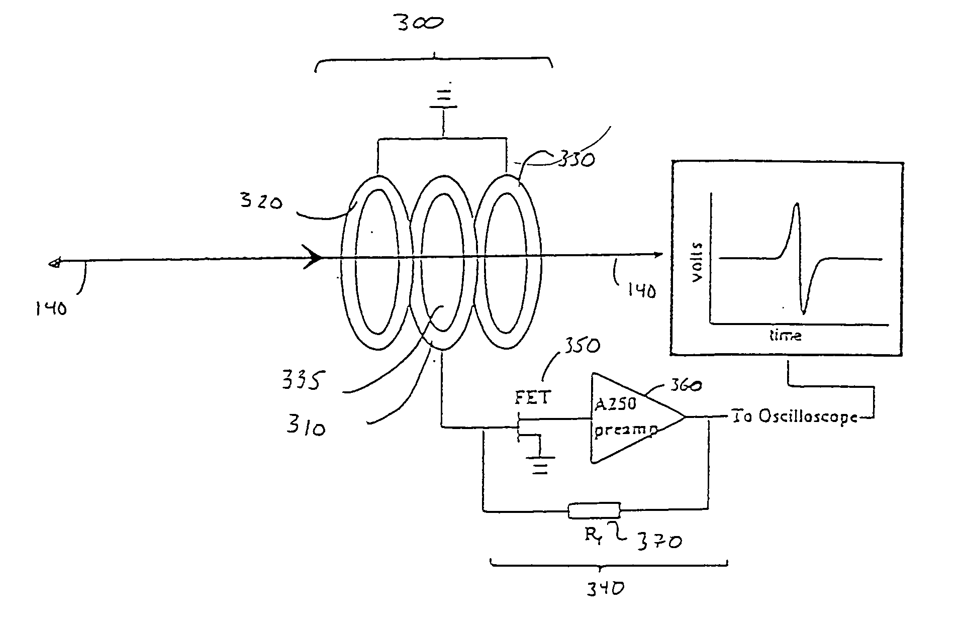
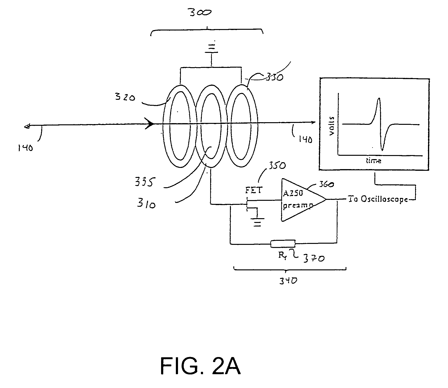
As a result of low overall efficiency, conventional mass spectrometric analysis of biomolecules requires larger quantities of biological samples and is unable to achieve the ultra low sensitivity needed for many important biological applications, such as single cell analysis of protein expression and post-translational modification.
Although the combination of modern ionization techniques and time-of-flight analysis methods has greatly expanded the mass range accessible by mass spectrometric methods, complementary ion detection methods suitable for the time of flight analysis of high molecular weight compounds remain less well developed.
Indeed, the effective upper limit of mass ranges currently accessible by MALDI-TOF and ESI-TOF analysis techniques are limited by the sensitivity of conventional ion detectors for high molecular weight ions.
In time-of-flight analysis, this corresponds to a decrease in sensitivity with increasing molecular weight.
A number of substantial limitations of this detection technique arise out of the impact-induced mechanism of MCP detectors governing secondary electron generation.
First, the yield of secondary electrons in a MCP detector decreases significantly as the velocity of ions colliding with the surface decreases.
Third, MCP detection is a destructive technique incapable of detecting the same ion or packet ions multiple times. Finally, MCP detectors generate electron cascades upon the impact of any species with the channel surface, including unwanted neutral species present in the ion flight tube.
As is apparent to those skilled in the art of mass spectrometry, the limitations associated with MCP detectors restrict the mass range currently accessible by MALDI-TOF and ESI TOF techniques, and hinder the quantitative analysis of samples containing high molecular weight biopolymers.
Although inductive detectors have been successfully applied to Fourier transform mass spectrometry, their use in time-of-flight mass analysis is substantially limited due to low sensitivity and poor detection efficiency.
Although the detector reportedly provides detection sensitivity that is independent of velocity, the single electrode arrangement does not provide a means of characterizing the velocities of ions prior to acceleration and time-of-flight analysis.
This limitation substantially reduces the mass resolution of the disclosed detector.
In addition, the methods and devices described are limited to detection of packets of gas phase ions, rather than single ions.
Because knowledge of pre-acceleration ion velocity is critical for the accurate determination of mass-to-charge ratio, uncertainty in this important parameter degrades mass resolution and absolute mass accuracy attainable.
Moreover, the spatial distribution of ions generated by the ion source and transmission scheme of the disclosed method substantially limits the sensitivity, mass analysis efficiency and detection efficiency attainable.
First, free expansion of ions prior to detection results in a wide spatial distribution of gas phase ions.
Second, the spatial distribution of the ions sampled impedes effective use of multiple inductive detectors in series because ion trajectories, which deviate substantially from the centerline of the detection scheme, will not be efficiently sampled by detectors positioned toward the end of a long flight path (>1 meter).
Finally, the detection technique described provides a relatively low detection sensitivity, limited to detecting ions having charge states of hundreds of elemental charges.
Collimators employing long distances from the apertures to the charged particle source result in charge particle streams having greater spatial collimation.
Such collimator arrangements, however, do not provide for efficient transfer of charge particles into the analysis and detection region.
Accordingly, use of spatially collimated charged particle sources comprising a series of apertures positioned long distances from the charge particle source results in charged particles losses.
Spatially collimated charged particles sources having electrostatic or electrodynamic lens systems, however, are susceptible to a number of aberrations including geometric aberrations, chromatic aberrations and aberrations caused by space charge effects.
Further, charged particles focused by conventional electrostatic or electrodynamic lens systems tend to undergo divergence upon passing through the focal point of the lens system.
Charged particles translating such trajectories will likely be lost at some unknown point during passage through the tubular detector due to collision with the walls and, therefore, the velocities of such particles may not be accurately determined.
Therefore, the distribution of actual flight paths of the charged particles analyzed introduces uncertainty into the measurement of particle velocity.
Therefore, particles having these trajectories will be lost in the detection and analysis region.

Method used


Image

  • Inductive detection for mass spectrometry
  • Inductive detection for mass spectrometry
  • Inductive detection for mass spectrometry

Examples


example 2

Ion Detection in Coincidence

[0134] The ability of the present invention to provide ion detection in coincidence was evaluated by analyzing liquid samples containing known quantities of polypeptide analytes using two inductive detectors sequentially positioned along the charged particle detection axis. The coincidence measurements confirm the ability of the inductive detectors to sensitively detect packets of ions without destroying them. In addition, the measurements show that the present invention is capable of efficient multiple detection of packets of ions.

[0135] Ions from polypeptide analytes were generated using a MALDI source and accelerated by an electrostatic potential applied by an electrode. A portion of the ions accelerated were sampled by an aperture positioned approximately 10 cm from the ion source. Upon translating through the sampling aperture, the ions were conducted through an analysis and detection region, wherein the ions passed through the axial bore of a first ...

example 3

Time-of-Flight Measurements Using a Fully Shielded Inductive Detector

[0140] In another aspect, the present invention comprises fully shielded inductive detectors having a shield element that entirely surrounds one or more sensing electrodes. The ability of fully shielded inductive detectors of the present invention to detect and analyze the flight times of charged particles generated from biopolymers was evaluated. Use of fully shielded inductive detectors provides better sensitivity and more accurate timing resolution compared to partially shielded inductive detectors.

[0141] FIG. 10 is a schematic diagram illustrating an exemplary fully shielded inductive detector of the present invention. As shown in FIG. 10, fully shielded inductive detector (900) comprises a tubular sensing electrode (910) having an axial bore concentrically positioned about charge detection axis (140), an insulator (920) and a shielding element (930) having a axial bore concentrically positioned about charge de...

example 4

MALDI Flight Tube Detector

[0150] The inductive detection systems of the present invention are high versatile and may be adapted to provide ion detection in coincidence for a wide range of commercial instruments, including MADLI ion sources and mass spectrometers, ESI ion sources and mass spectrometers, tandem mass spectrometers, TOF-TOF instruments, single quandrupole mass spectrometers, triple quadrupole mass spectrometers, linear ion traps, quadrupole--time-of-flight mass spectrometers and Fourier transform ion cyclotron resonance mass spectrometers. FIG. 12 is a schematic diagram of an exemplary inductive detector of the present invention well-suited for incorporation into conventional mass spectrometers utilizing time-of-flight detection. The exemplary detector (1100) comprises first and second inductive detectors (1101) and (1102), preferentially fully shielded inductive detectors, which are housed in housing (1110). In a preferred embodiment, housing (1110) is designed such th...


PUM


Abstract

The invention provides devices, device configurations and methods for improved sensitivity, resolution and efficiency in mass spectrometry, particularly as applied to biological molecules, including biological polymers, such as proteins and nucleic acids. More particularly, the invention provides methods and devices for analyzing and detecting electrically charged particles, especially suitable for gas phase ions generated from high molecular weight compounds. In one aspect, the invention provides devices and methods for determining the velocity, charged state or both of electrically charged particles and packets of electrically charged particles. In another aspect, the invention provides methods and devices for the time-of-flight analysis of electrically charged particles comprising spatially collimated sources. In another aspect, the invention relates to multiple detection using inductive detectors, improved methods of signal averaging and charged particle detection in coincidence.

Description

[0001] This application claims priority under 35 U.S.C. 119(e) to provisional patent application 60 / 429,844, filed Nov. 27, 2002, which is hereby incorporated by reference in its entirety to the extent not inconsistent with the disclosure herein.BACKGROUND OF INVENTION[0003] Over the last several decades, mass spectrometry has emerged as one of the most broadly applicable analytical tools for detection and characterization of a wide class of molecules, ions and aggregates of molecules, ions or both. Mass spectrometric analysis is applicable to almost any species capable of forming an ion in the gas phase, and, therefore, provides perhaps the most universally applicable method of quantitative analysis. In addition, mass spectrometry is a highly selective technique especially well suited for the analysis of complex mixtures comprising a large number of different compounds in widely varying concentrations. Moreover, mass spectrometric methods provide very high detection sensitivity, ap...

Claims


Application Information

Patent Timeline
IPC IPC(8): B01D59/44H01J49/00H01J49/06H01J49/16
CPCH01J49/06H01J49/027
Inventor WESTPHALL, MICHAEL S.SMITH, LLOYD M.
Owner WISCONSIN ALUMNI RES FOUND
Learn More