Hydrogen recycle for high temperature fuel cells

a high-temperature fuel cell and hydrogen recycling technology, applied in the direction of fuel cells, fuel cell auxiliaries, by adsorption, etc., can solve the problems of degradation of cell voltage, prior art sofc systems face even more challenging temperature regimes, limitations of high-temperature operation, etc., to achieve a high ratio of h2 to h2o, improve voltage efficiency and output

Inactive Publication Date: 2004-10-07
QUSIR TECH
View PDF99 Cites 70 Cited by
  • Summary
  • Abstract
  • Description
  • Claims
  • Application Information

AI Technical Summary

Benefits of technology

[0025] In an embodiment of the present disclosure, a high temperature fuel cell electrical generation system is provided that is adapted to enable selective generation of electrical power, and / or hydrogen fuel, and / or useable heat, allowing flexible operation of the generation system wherein the generation system may additionally incorporate means for mitigation of "greenhouse" gas and other environmentally deleterious gas emissions, and for enhancing overall efficiency of operation to increase sustainability of fuel resource use. In such an embodiment, the high temperature fuel cell may be either a MCFC or a SOFC.
[0057] 4. low steam concentration inhibits conversion of CH4 and CO to CO2, thus ensuring that the steam reforming reaction within the anode channel is most highly endothermic to take up fuel cell waste heat for improved overall heat balance.

Problems solved by technology

Prior art MCFC systems have limitations associated with their high temperature operation, and with their inherent need to supply carbon dioxide to the cathode while removing it from the anode.
Prior art SOFC systems face even more challenging temperature regimes, and are disadvantaged by the degradation of cell voltages at very high temperatures under conventional operating conditions.
Unfortunately, the reaction depletes the oxygen and carbon dioxide in the cathode channel and depletes hydrogen in the anode channel while rapidly increasing the backpressure of carbon dioxide in the anode channel.
This degrades the electrical efficiency of the system, while increasing the heat that must be converted at already lower efficiency by the thermal bottoming cycle.
Prior art MCFC systems do not provide any satisfactory solution for this problem which compromises attainable overall efficiency.
Despite repeated attempts to devise an effective technology and method to maximize reactant concentrations, and minimize product accumulation in both the anode and cathode circuits that would be compatible with MCFC operating conditions, no such attempt has been adequately successful.
This approach has limitations.
Even more of the original fuel value is unavailable for relatively efficient electrochemical power generation, in view of additional combustion whose heat can only be absorbed usefully by the thermal bottoming cycle.
Also, the oxygen / nitrogen ratio of the cathode gas is even more dilute than ambient air, further reducing cell voltage and hence transferring more power generation load less efficiently onto the thermal bottoming plant
Previously, application of displacement purge processes has been limited by compatibility of components A, B and C. Even within the context of an overall separation being achieved, some intimate mixing will take place due to axial dispersion in the adsorbers, fluid holdup in gas cavities, and leakage across fluid seals and valves.
In that application, displacement purge using air (or any oxygen-containing gas with oxygen appearing as a component C) would in the prior art have been impracticable owing to unacceptable hazards of cross-contamination between hydrogen and oxygen.

Method used


Image

  • Hydrogen recycle for high temperature fuel cells
  • Hydrogen recycle for high temperature fuel cells
  • Hydrogen recycle for high temperature fuel cells

Examples


Embodiment Construction

[0067] FIGS. 1-4

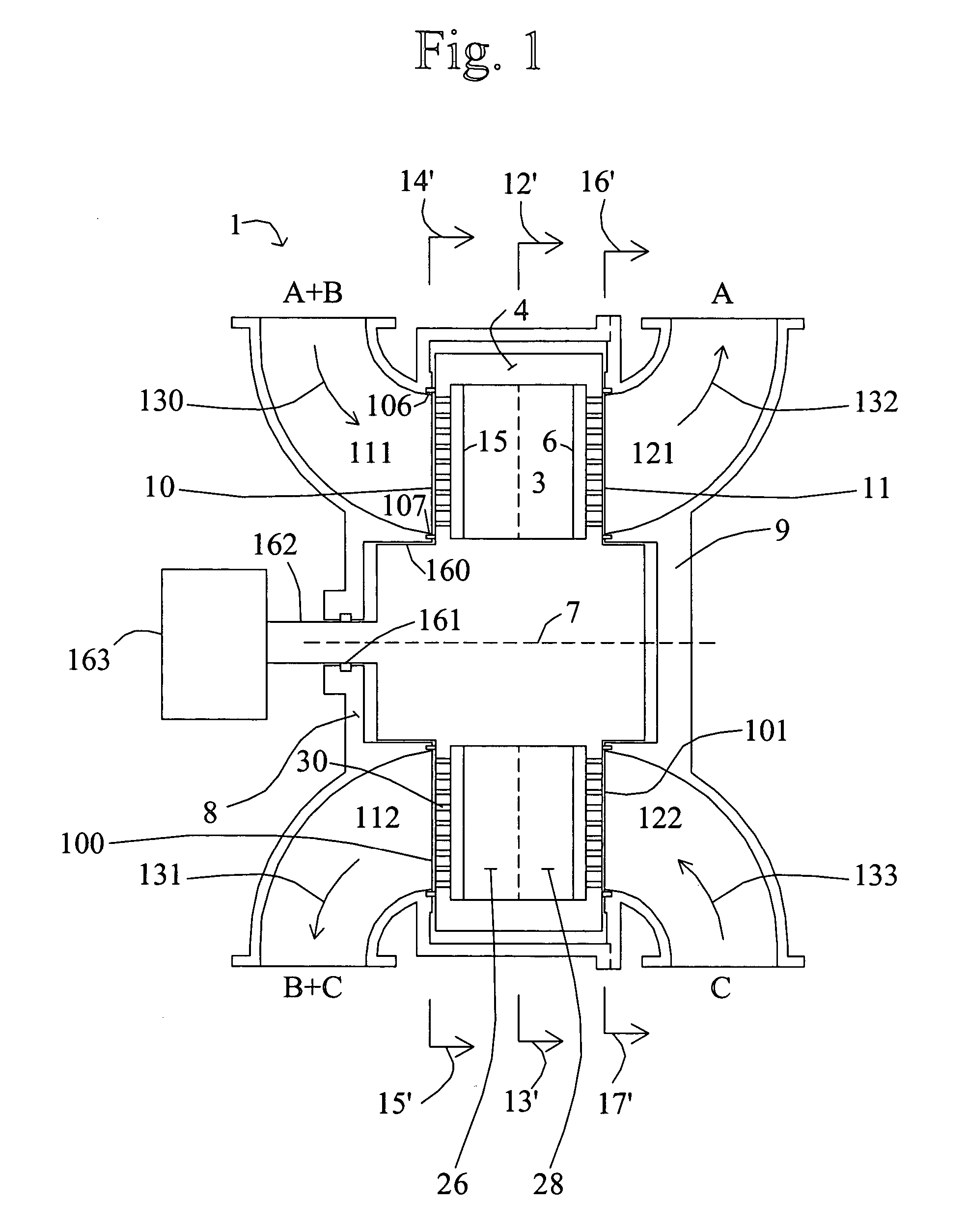
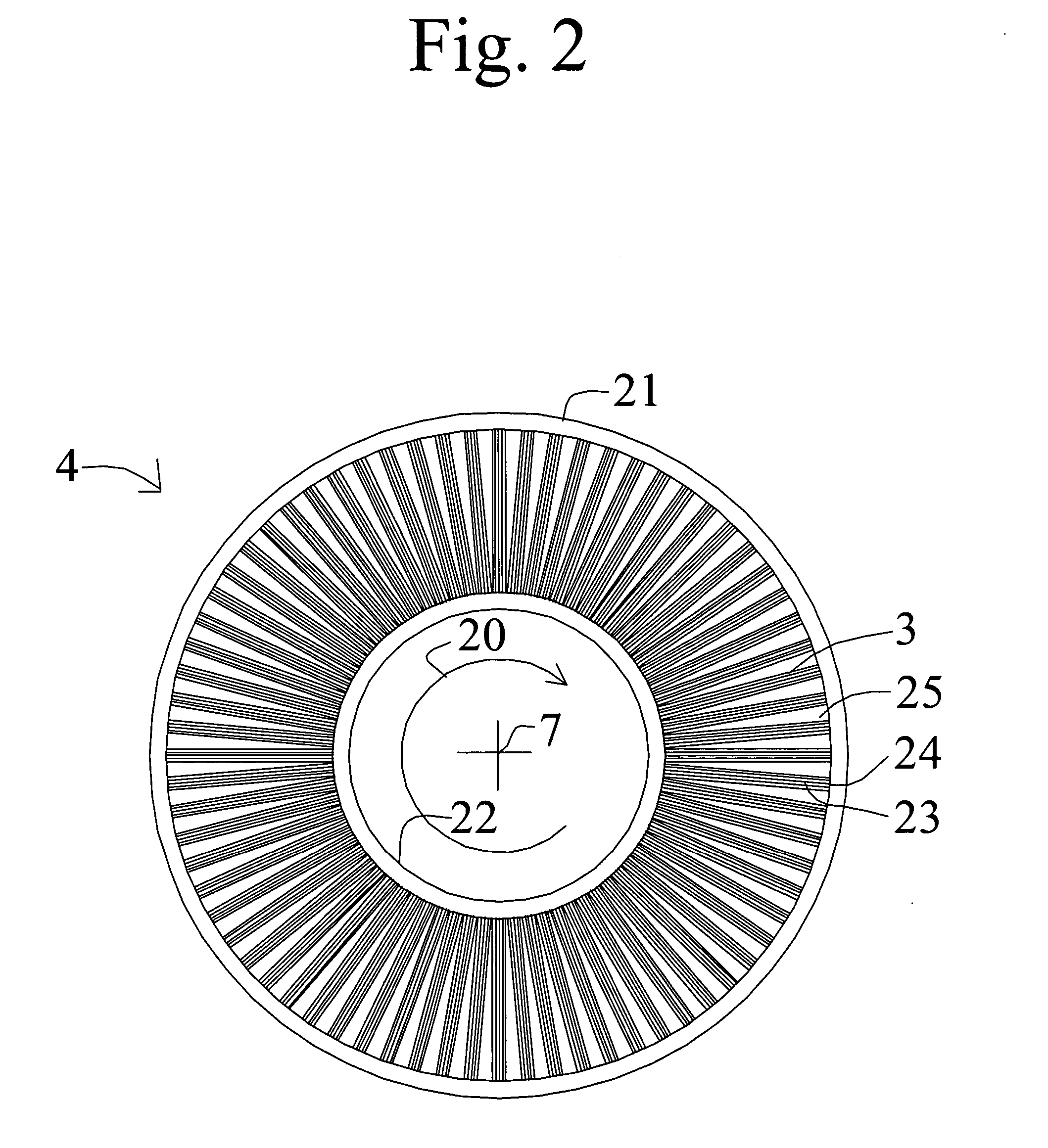
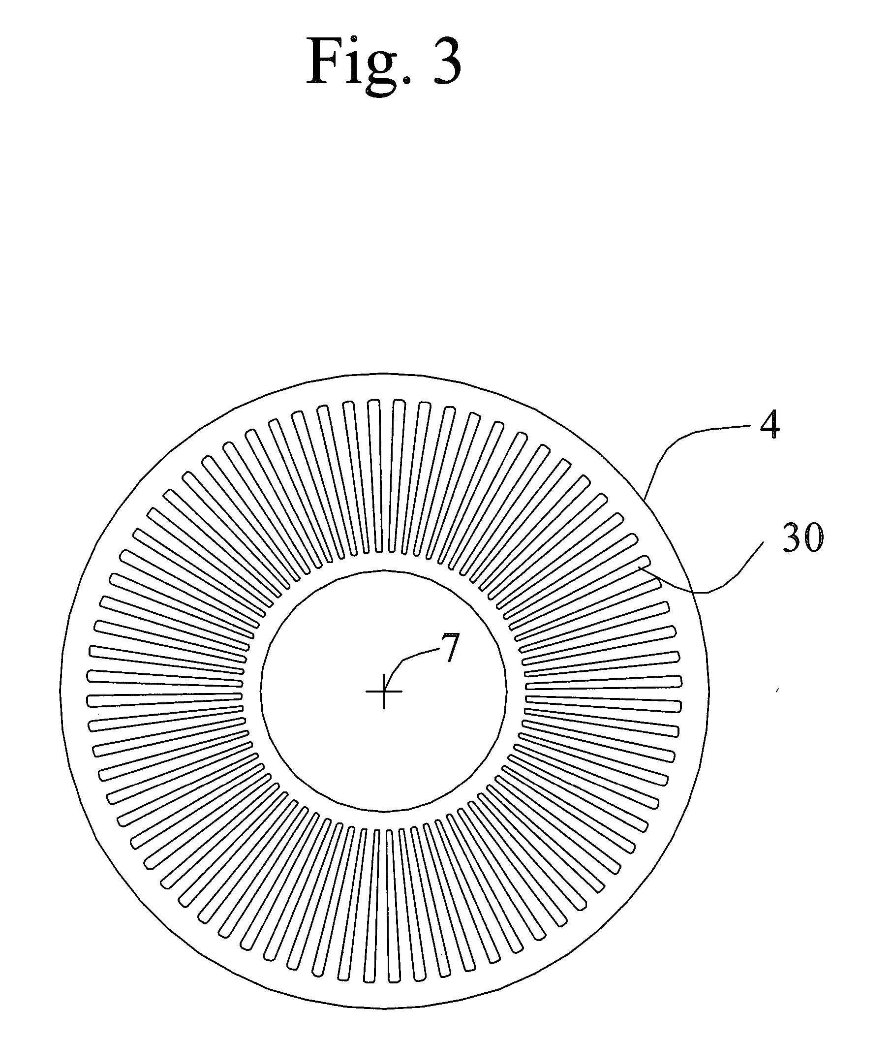
[0068] A hydrogen-enrichment rotary adsorption module with displacement purge regeneration is described below in connection with FIGS. 1-4. As used herein, a "rotary adsorption module" includes, but is not limited to, either a device wherein an array of adsorbers rotates relative to a fixed valve face or stator or a device wherein the valve face or stator rotates relative to an array of adsorbers. Illustrated embodiments have the adsorbers mounted in a rotor, with the rotor in a housing which is a stator with fixed valve faces.

[0069] FIG. 1 shows a rotary adsorption module 1, which includes a number "N" of adsorbers 3 or adsorber channels 3 in adsorber housing body 4. Each adsorber has a first end 5 and a second end 6, with a flow path therebetween contacting an adsorbent over which a gas component B is more readily adsorbed relative to a component A and a component C which are less readily adsorbed. The adsorbers are deployed in an axisymmetric array about axis 7 of...


PUM

PropertyMeasurementUnit
operating temperatureaaaaaaaaaa
operating temperaturesaaaaaaaaaa
temperatureaaaaaaaaaa

Abstract

High temperature fuel cell electrical generation systems are provided that are adapted to enable selective generation of electrical power, and / or hydrogen fuel, and / or useable heat, allowing flexible operation of the generation system. In such embodiments, the high temperature fuel cell may be either a MCFC or a SOFC. The disclosed systems relate to high temperature fuel cells exploiting gas separation devices in which a first gas mixture is to be separated so that a first product of the separation is enriched in a first component, while a second component is mixed with a displacement purge stream to form a second gas mixture, with provision to prevent cross contamination of purge gas components into the first product stream. The process may be applied to hydrogen (component A) enrichment from syngas mixtures such as fuel cell anode exhaust, where dilute carbon dioxide (component B) is to be rejected such as to the atmosphere or for recycle to the fuel cell cathode in the case of molten carbonate fuel cells, by purging with cathode exhaust oxygen-depleted air (as component C).

Description

PRIORITY CLAIM[0001] This application claims the benefit of U.S. Provisional Application 60 / 451,057, filed Feb. 26, 2003, and incorporated herein by reference.FIELD[0002] This application is related to adsorptive gas separation, and in particular rotary pressure swing adsorption (PSA), as well as fuel cell applications, and QuestAir Technologies' related patent applications, including Nos. 09 / 591,275, 09 / 808,715, 60 / 323,169, and 60 / 351,798, the disclosures of which are incorporated herein by reference.[0003] The present disclosure relates to high temperature fuel cell systems, such as solid oxide fuel cell (SOFC) and molten carbonate fuel cell (MCFC) systems exploiting gas separation devices in which a first gas mixture comprising components A (e.g. hydrogen) and B (e.g. carbon dioxide) is be separated so that a first product of the separation is enriched in component A, while component B is mixed with a third gas component C (e.g. air, oxygen-enriched air or oxygen-depleted air) co...

Claims


Application Information

Patent Timeline
Patent Type & Authority Applications(United States)
IPC IPC(8): B01DB01D53/06H01M2/00H01M2/02H01M2/14H01M8/00H01M8/04H01M8/10H01M8/12H01M8/14H01M8/18
CPCB01D53/0462B01D53/047B01D53/0476B01D53/06B01D53/261B01D2253/108B01D2253/25B01D2253/3425B01D2256/10B01D2256/12B01D2256/16B01D2257/504B01D2257/70B01D2257/80B01D2258/0208B01D2259/40001B01D2259/40005B01D2259/4566H01M8/04097H01M8/04231H01M8/0668H01M8/0687H01M2008/1293H01M2008/147Y02C10/08Y02E60/50Y02E60/525Y02E60/526Y02C20/40
Inventor KEEFER, BOWIE G.BABICKI, MATTHEW L.
Owner QUSIR TECH
Why Eureka
Try Eureka