Electrophoretic particles, and processes for the production thereof

a technology of electrotrophoretic particles and processes, applied in the field of electrotrophoretic particles, can solve the problems of rapid white state degradation, widespread use of electrotrophoretic particles, and inadequate service life of these displays

Inactive Publication Date: 2005-01-06
E INK CORPORATION
View PDF99 Cites 144 Cited by
  • Summary
  • Abstract
  • Description
  • Claims
  • Application Information

AI Technical Summary

Benefits of technology

In another aspect, this invention provides a copper chromite particle having a polymer chemically bonded to, or cross-linked around, the particle. Preferably, the polymer is chemically bonded to the particle. The polymer coating should correspond to between 5 and 500 mg/m2 of pigment surface area (as measured by the BET technique or other suitable method), more preferably to between 10 and 100 mg/m2, and most preferably to between 20 and 100 mg/m2. The polymer may comprise from about 1 to about 15 percent by weight, preferably from about 2 to about 8 percent by weight, of the particle. The polymer (or a residue of a functionalization agent bonding the polymer to the particle, as previously discussed) may comprise charged or chargeable groups, for example amino groups. The polymer may comprise a main chain and a plurality of side chains extending from the main chain, each of the side chains comprising a

Problems solved by technology
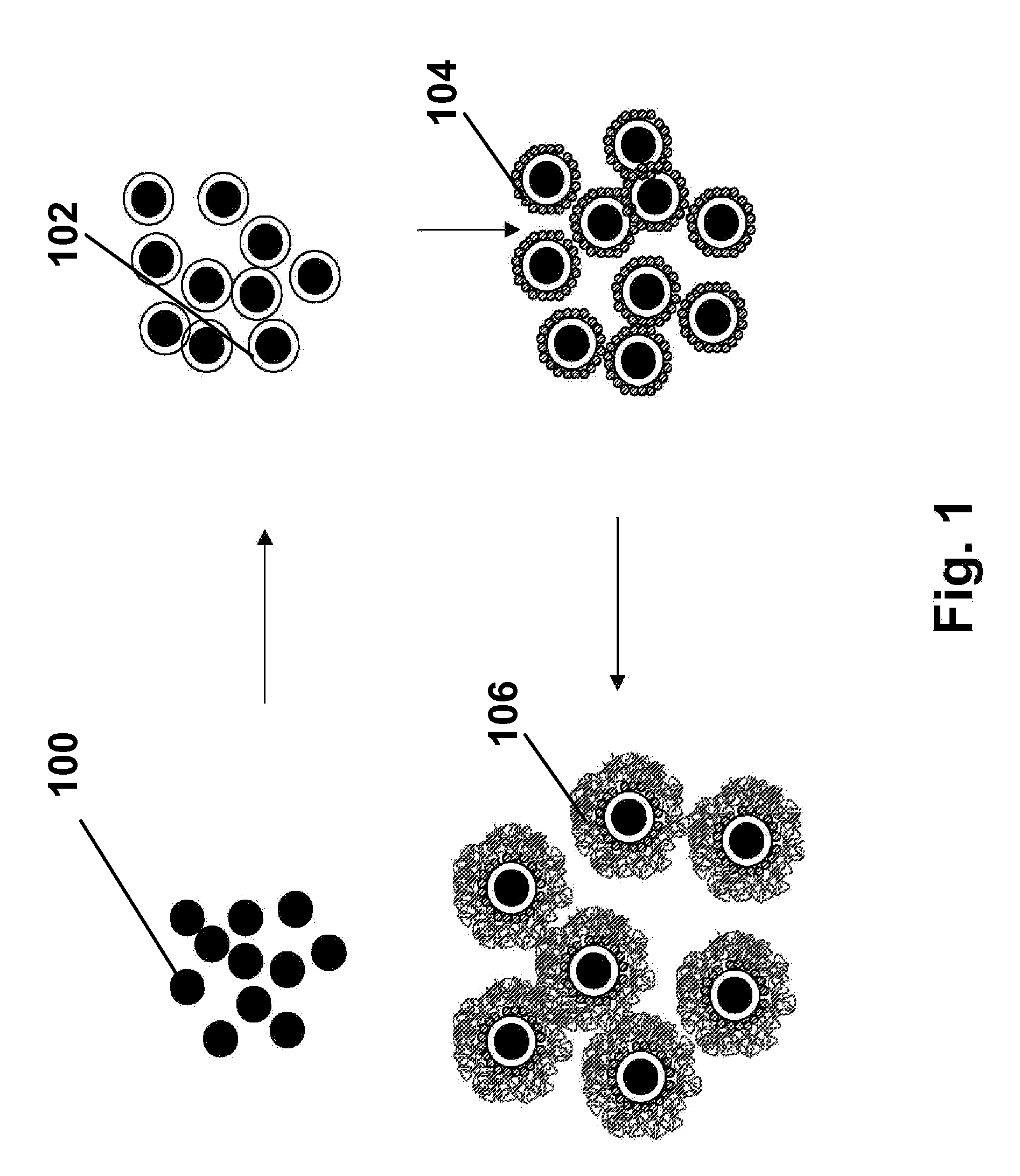
Nevertheless, problems with the long-term image quality of electrophoretic displays have prevented their widespread usage.
For example, particles that make up electrophoretic displays tend to settle, resulting in inadequate service-life for these displays.
Among the remaining problems of encapsulated electrophoretic displays are so-called “rapid white state degradation”, a relatively rapid decline in the reflectivity of the white optical state of the display during the first few days of operation.
Another problem, which is discussed in detail in the aforementioned 2003/0137521 and WO 03/107315, is so-called “dwell state dependency”, which causes the change in optical state of an electrophoretic medium produced by a specific waveform to vary depending upon the time for which the electrophoretic medium has been in a particular optical state before the waveform is applied.
However, the present inventors and their co-workers have discovered that the aforementioned problems with prior art electrophoretic displays are associated with the use of carbon black for the black electrophoretic particles.
Carbon black has a complex and poorly understood surface chemistry, which may vary widely with the specific raw material (typically petroleum) and the exact process used for the carbon black production.
Hence, it is difficult to ensure consistent surface properties of carbon black from batch to batch.
This is especially problematic in electrophoretic displays, since the electrophoretic particles used are typically so small (of the order of 1 μm) that their properties are dominated by the properties of their surfaces.
It has also been discovered (although this information is not disclosed in the prior art) that carbon black presents certain peculiar difficulties in obtaining proper charging of particles in

Method used


Image

  • Electrophoretic particles, and processes for the production thereof
  • Electrophoretic particles, and processes for the production thereof
  • Electrophoretic particles, and processes for the production thereof

Examples


example 1

Silica Coating of Copper Chromite Pigment

A dispersion was prepared consisting of Shepherd Black 1G (50 g), water (420 mL) and sodium silicate solution (6 mL of a solution containing approximately 14% of sodium hydroxide and 27% of silica, available from Aldrich Chemical Company); the dispersion was sonicated for one hour. The dispersion was then added to a 1 L three-necked flask equipped with a stirring bar, reflux condenser (open to the air) and two addition funnels equipped with needle-valve control stopcocks. The flask was partially immersed in a silicone oil bath and heated to 100° C. with rapid stirring over a period of one hour. During this heating period, the first addition funnel was charged with 0.22M sulfuric acid (150 mL) and the second with a mixture of the aforementioned sodium silicate solution (11 mL) and water (70 mL). After the silicone oil bath reached 100° C., the two solutions in the addition funnels were simultaneously added to the dispersion in the flask over...

example 2

Silane Treatment of Silicated Copper Chromate Pigment

The silica-coated copper chromite pigment produced in Example 1 was used without further treatment in a silanization process. For this purpose, a mixture of 300 ml of ethanol, 30 ml of water and 40 g of a 40 weight percent solution of N-[3-(trimethoxysilyl)propyl]-N′-(4-vinylbenzyl)ethylenediamine hydrochloride (available from United Chemical Technologies, 2731 Bartram Road, Bristol, Pa. 19007-6893) in methanol was stirred rapidly for 7 minutes, the pigment was added thereto, and the resultant mixture was stirred for a further 5 minutes. The resultant suspension was poured into plastic bottles and centrifuged at 3500 rpm for 30 minutes. The supernatant liquor was decanted, and the silanized pigment redispersed in ethanol and centrifuged at 3500 rpm for 30 minutes, and the liquid decanted. The washing was repeated, and the pigment finally dried in air for 18 hours, then under vacuum at 70° C. for 2 hours. The amount of surface fu...

example 3

Polymer Coating of Silanized Copper Chromate Pigment

The silanized pigment produced in Example 2 (50 g) was placed in a round-bottomed flask with toluene (50 g) and 2-ethylhexyl methacrylate monomer (50 g). The resultant mixture was stirred rapidly under a nitrogen atmosphere (argon may alternatively be used) for 20 minutes, then slowly heated to 50° C. and AIBN (0.5 g in 10 ml of toluene) added quickly. The suspension was then heated to 65° C. and stirred at this temperature under nitrogen for a further 18 hours. The resultant suspension was poured into plastic bottles, the flask being washed out with ethyl acetate to remove residual product and the ethyl acetate solution added to the bottles. The bottles were centrifuged at 3500 rpm for 30 minutes. The supernatant liquor was decanted, and the polymer-coated pigment re-dispersed in ethyl acetate and centrifuged at 3500 rpm for 30 minutes, and the liquid decanted. The washing was repeated, and the pigment dried in air until a worka...


PUM

PropertyMeasurementUnit
Timeaaaaaaaaaa
Percent by massaaaaaaaaaa
Diameteraaaaaaaaaa

Abstract

Copper chromite particles can advantageously be used as black particles in electrophoretic media and displays. Preferably, the copper chromite particles are coated with a silica coating and a polymer coating.

Description

BACKGROUND OF INVENTION This invention relates to electrophoretic particles (i.e., particles for use in an electrophoretic medium) and processes for the production of such electrophoretic particles. This invention also relates to electrophoretic media and displays incorporating such particles. More specifically, this invention relates to novel black or dark colored electrophoretic particles. Particle-based electrophoretic displays, in which a plurality of charged particles move through a suspending fluid under the influence of an electric field, have been the subject of intense research and development for a number of years. Such displays can have attributes of good brightness and contrast, wide viewing angles, state bistability, and low power consumption when compared with liquid crystal displays. The terms “bistable” and “bistability” are used herein in their conventional meaning in the art to refer to displays comprising display elements having first and second display states ...

Claims


Application Information

Patent Timeline
IPC IPC(8): B41J3/407C09B67/08C09C1/00C09C1/24C09C1/34C09C3/00C09C3/10C09C3/12G02B26/02G02F1/133G02F1/1333G02F1/1334G02F1/1343G02F1/1345G02F1/135G02F1/1365G02F1/167G04G21/04G06F3/14G06F3/147G09F9/302G09F9/37H01L27/12H01L27/28H01L51/00H01L51/05H01L51/30
CPCB41J3/4076Y10T428/2998B82Y30/00C01P2002/88C01P2004/32C01P2004/51C01P2004/61C01P2004/62C01P2004/64C01P2004/82C01P2004/84C01P2006/10C01P2006/12C01P2006/40C01P2006/60C01P2006/80C01P2006/90C09B67/0013C09C1/00C09C1/34C09C3/006C09C3/10C09C3/12G02B26/026G02F1/133305G02F1/133348G02F1/13336G02F1/1334G02F1/1343G02F1/1345G02F1/135G02F1/1365G02F1/167G02F1/172G02F2001/1678G02F2202/12G02F2202/28G06K19/07703G09F9/302G09F9/372H01L27/12H01L27/28H01L51/0036H01L51/0038H01L51/0045H01L51/005H01L51/0051H01L51/0052H01L51/0077H01L51/0078H01L51/0512H01L51/0545Y10T428/2991B82Y10/00G03G17/02G03G17/04G03G17/06C25D13/02C09B67/0097C23C18/1212C23C18/1229C23C18/1295H10K85/114H10K85/20H10K85/113H10K85/611H10K85/60H10K85/615H10K85/311H10K85/30H10K10/462H10K10/466H10K19/00
Inventor PULLEN, ANTHONY EDWARDWHITESIDES, THOMAS H.HONEYMAN, CHARLES H.COMISKEY, BARRETTALBERT, JONATHAN D.
Owner E INK CORPORATION
Why Eureka
Try Eureka