Photolytic oxygenator with carbon dioxide fixation and separation

a technology of oxygenator and carbon dioxide, applied in the direction of separation process, lighting and heating apparatus, heating types, etc., can solve the problems of high risk of sudden release of large amounts of pure oxygen gas, high heat required and high risk of pure oxygen gas capture, storage and disposal, etc., to improve o2 yield and co2 clearance

Inactive Publication Date: 2005-01-20
BATTELLE MEMORIAL INST
View PDF4 Cites 29 Cited by
  • Summary
  • Abstract
  • Description
  • Claims
  • Application Information

AI Technical Summary

Benefits of technology

In a further aspect, the present invention relates to the direct photolytic conversion of water to liquid phase oxygen (dissolved oxygen), with commensurate clearance of carbon dioxide. A test flow cell is provided comprising a conductive coating of vacuum-deposited titanium (Ti) metal, adherent TiO2 (anatase), and MnO2, applied as a laminant to a glass substrate. Long wavelength (low energy) UV laser light, directed to the transparent glass substrate, reproducibly resulted in the generation of H2O2, an active form of oxygen (active oxygen), which was subsequently converted, by the catalytic action of MnO2, to dissolved oxygen. Oxygen gas is then extracted from the dissolved oxygen through an oxygen gas separator and collected or channeled to a closed or constricted living environment. Additionally, carbon dioxide present in the closed or constricted living environment is removed by reacting the carbon dioxide with other carbon sources and catalysts to form carbonate solids. Based on these results and others, the photolytic cell or module may be used, employing multiple parallel photolytic surfaces to improve O2 yield and CO2 clearance.

Problems solved by technology

Oxygen depletion in confined spaces has always been a problem.
While hydrogen and oxygen are produced, the simultaneous production of hydrogen results in problems concerning its safe capture, storage and disposal.
In this operation the high heat required and sudden release of large amounts of pure oxygen gas are highly hazardous and limits the usefulness of this technology.
Potassium Hydroxide (KOH) Electrolysis—This technology is also hazardous as it emits explosive mixtures of O2 and H2 gases, since KOH is strongly caustic and corrosive.
However, this material is hazardous due to it being a caustic fine powder.
It is spread over the floor to generate a high surface area whereupon it leads to possible contact and / or ingestion by the crew causing illness and potential lung damage.
These units are complicated processes and so are difficult to control.
They also require large amounts of space and are heavy.

Method used


Image

  • Photolytic oxygenator with carbon dioxide fixation and separation
  • Photolytic oxygenator with carbon dioxide fixation and separation
  • Photolytic oxygenator with carbon dioxide fixation and separation

Examples


example 1

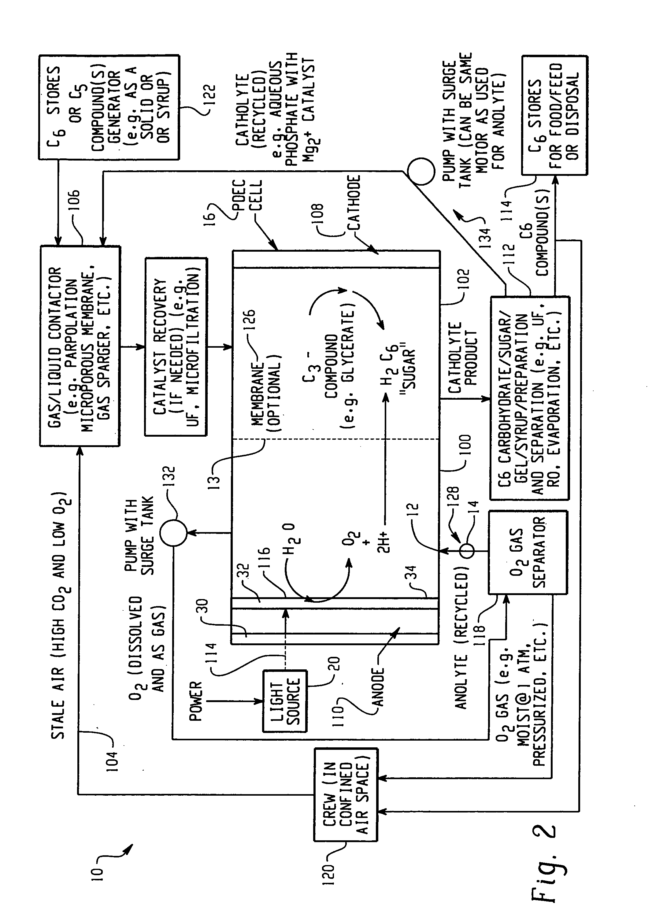
In this example, oxygen is produced and carbon dioxide is removed from stale air using water, C3 or C5 compounds and photolytic energy. Referring now to FIG. 2, a PDEC cell 16 is used for the central reaction of producing oxygen in the anode compartment 100 and producing a C6 compound, such as hexose sugar, from carbon dioxide in the cathode compartment 102.

In this regard, stale air (high in CO2 and low in O2) 104 is first contacted with a liquid such as a recycled catholyte (e.g. aqueous phosphate with Mg2+ catalyst) in gas / liquid contactor 106 to convert the carbon dioxide into dissolved form in the liquid, normally CO2 (aq), but could also be HCO3, H2CO3 and / or CO32−. The gas / liquid contactor 106 can be in a counter flowing percolating bed, a micro-porous membrane, gas sparger, etc.

The dissolved carbon dioxide catalyst, glycerate, and pentose and the liquid then flow into the cathode compartment 102 of the PDEC cell 16. Pentose can also be contained in the contacting liquid ...

example 2

This example illustrates the production of oxygen and the reduction of CO2 through the formation of a C3 compound intermediary. Referring now to FIG. 3, a PDEC cell 16 is used for the central reaction of producing oxygen and reducing the carbon dioxide obtained from the confined space 120. Stale air 104 is first contacted with a liquid such as aqueous brine containing a α-keto pentose containing a catalyst typically of mixtures of Mg2+ / PO43− electrolyte gas / liquid at contactor 106 to convert the carbon dioxide into dissolved form in the liquid. This contact at contactor 106 may be in a counter flowing circulating bed, a porous membrane, or in a percolating bed, etc. The dissolved carbon dioxide, e.g. now in the carbon dioxide laden electrolyte, is also contacted with the C5 pentose obtained from stores 122, also containing a catalyst, e.g. rubisco type enzymatic catalyst or a derivative compound for this enzyme. In this manner the CO2 and α-keto ribulose is converted to two C3 glyc...


PUM

PropertyMeasurementUnit
volume areaaaaaaaaaaa
light transparentaaaaaaaaaa
transparentaaaaaaaaaa

Abstract

Apparatus for oxygenating an enclosed space as well as removing carbon dioxide from the enclosed space.

Description

FIELD OF THE INVENTION The present invention is directed to a photolytically driven electrochemical (“PDEC”) oxygenator and carbon dioxide remover that uses light energy to achieve gas exchange in various media. It finds particular application in providing a proper physiological gas environment for humans, animals and microorganisms. It is also to be appreciated that the invention finds further particular applications in confined space areas such as the crew or cabin space of a submarine, space station, interplanetary vehicle, extraterrestrial vehicle, subterranean mine, cave or tunnels or other confined volume areas. BACKGROUND OF THE INVENTION Oxygen depletion in confined spaces has always been a problem. Human beings need a constant supply of oxygen and the concomitant removal of carbon dioxide to live and function. When humans, microorganisms or other animals are in confined spaces where the flow of gases from the atmosphere is impeded, the aforementioned supply of oxygen and ...

Claims


Application Information

Patent Timeline
Patent Type & Authority Applications(United States)
IPC IPC(8): A61M1/14A62B13/00B01D5/00B01D53/86B01J19/08B01J19/12C02F1/20F01L
CPCA62B13/00B01D53/864A61M1/327B01D2257/504F24F2003/1692B01D2255/802F24F8/60
Inventor MONZYK, BRUCE FBURCKLE, ERIC C.
Owner BATTELLE MEMORIAL INST
Why Eureka
Try Eureka