[0021] The present invention is directed to a
mass-producible passively modelocked
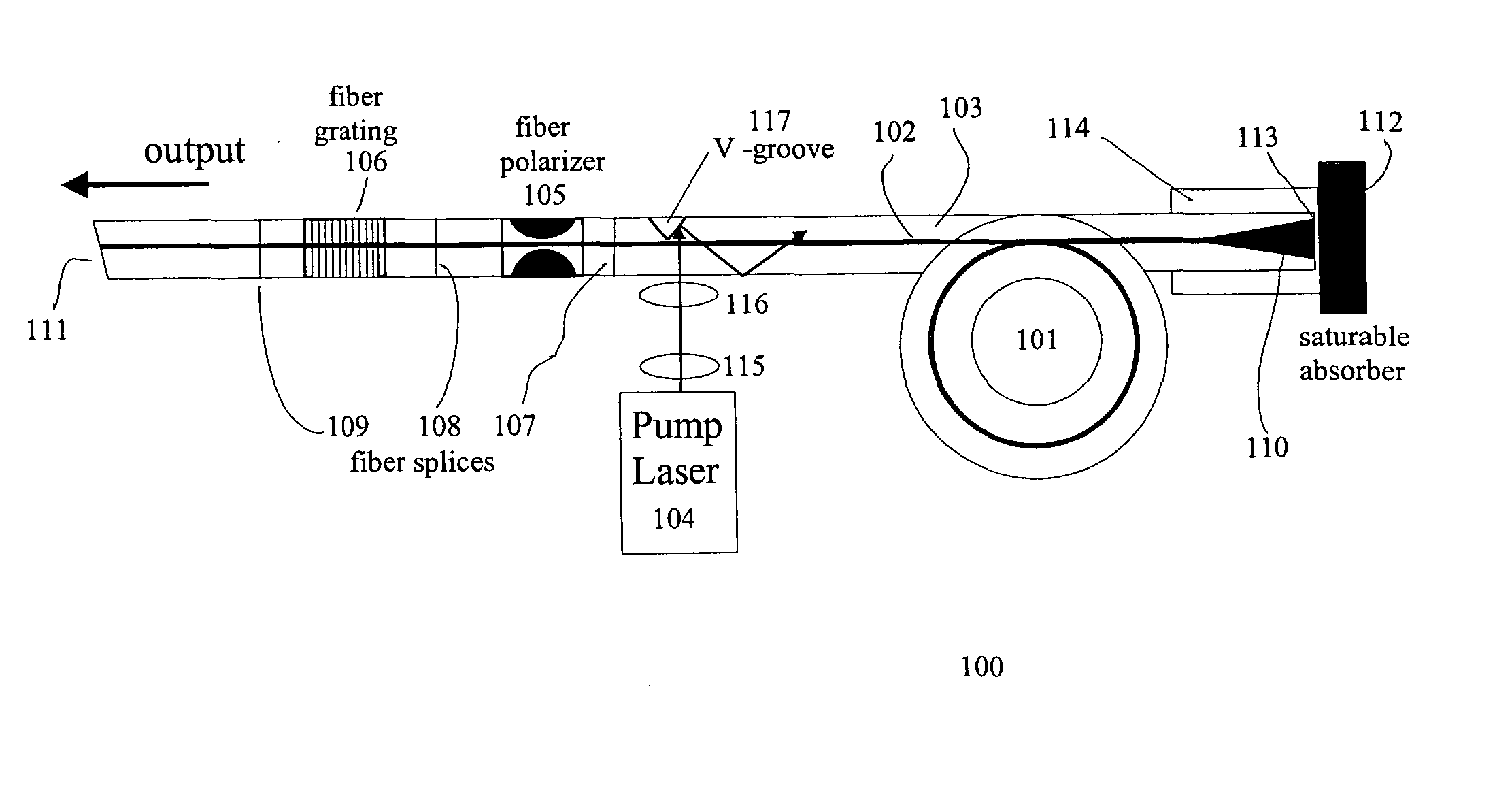
fiber laser. By incorporating apodized fiber Bragg gratings, integrated fiber polarizers and concatenated sections of polarization-maintaining and non-polarization-maintaining fibers, a fiber pig-tailed, linearly polarized output can be readily obtained from the laser. By further matching the dispersion value of the
fiber Bragg grating to the inverse, or negative, of the dispersion of the intra-cavity fiber, the generation of optimally short pulses with a large optical bandwidth can be induced. In this regard, either positive dispersion fiber in conjunction with negative dispersion
fiber gratings or negative dispersion fiber in conjunction with positive dispersion
fiber gratings can be implemented. Preferably, the dispersion characteristics of the
fiber Bragg grating and the dispersion characteristics of the rest of the intra-cavity elements are matched to within a factor of three. Even more preferably, these characteristics are matched within a factor of two, or within a factor in the range of 1.0 to 2.0. Also preferably, the Bragg
grating has a
chirp rate greater than 80 nm / cm. More preferably, the Bragg
grating has a
chirp rate greater than 160 nm / cm. Most preferably, the Bragg
grating has a
chirp rater greater than 300 nm / cm. To maximize the output power and the pulse repetition rate, the use of wide-bandwidth fiber Bragg gratings with low absolute dispersion is preferable. These fiber Bragg gratings are also used as end-mirrors for the cavity and allow the transmission of pump light to the intra-cavity
gain fiber. The fiber Bragg gratings are conveniently produced using phase masks.
[0022] Alternatively, fiber couplers can be used inside the fiber cavity. Generally, sections of polarization-maintaining and non-polarization-maintaining fiber can be concatenated inside the fiber cavity. The non-polarization-maintaining section should then be short enough so as not to excessively perturb the polarization state. Intra-cavity sections of non-polarization-maintaining fiber preferably comprise all-fiber polarizers to lead to preferential oscillation of one
linear polarization state inside the cavity. Similarly, when directly concatenating polarization-maintaining fiber sections, the length of the individual section should be long enough to prevent coherent interactions of pulses propagating along the two polarization axes of the polarization-maintaining fibers, thereby ensuring a maximum in pulse stability.
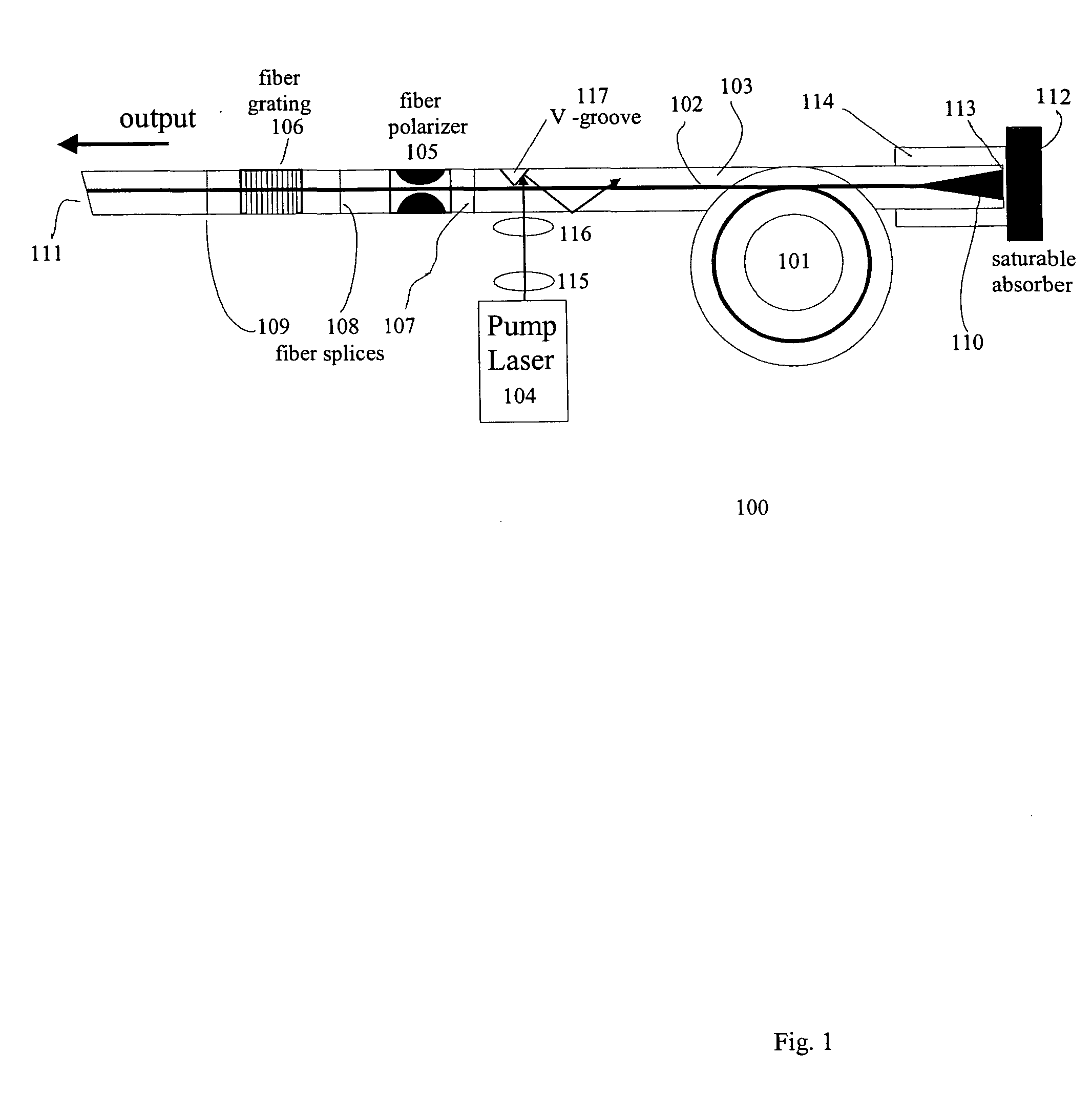
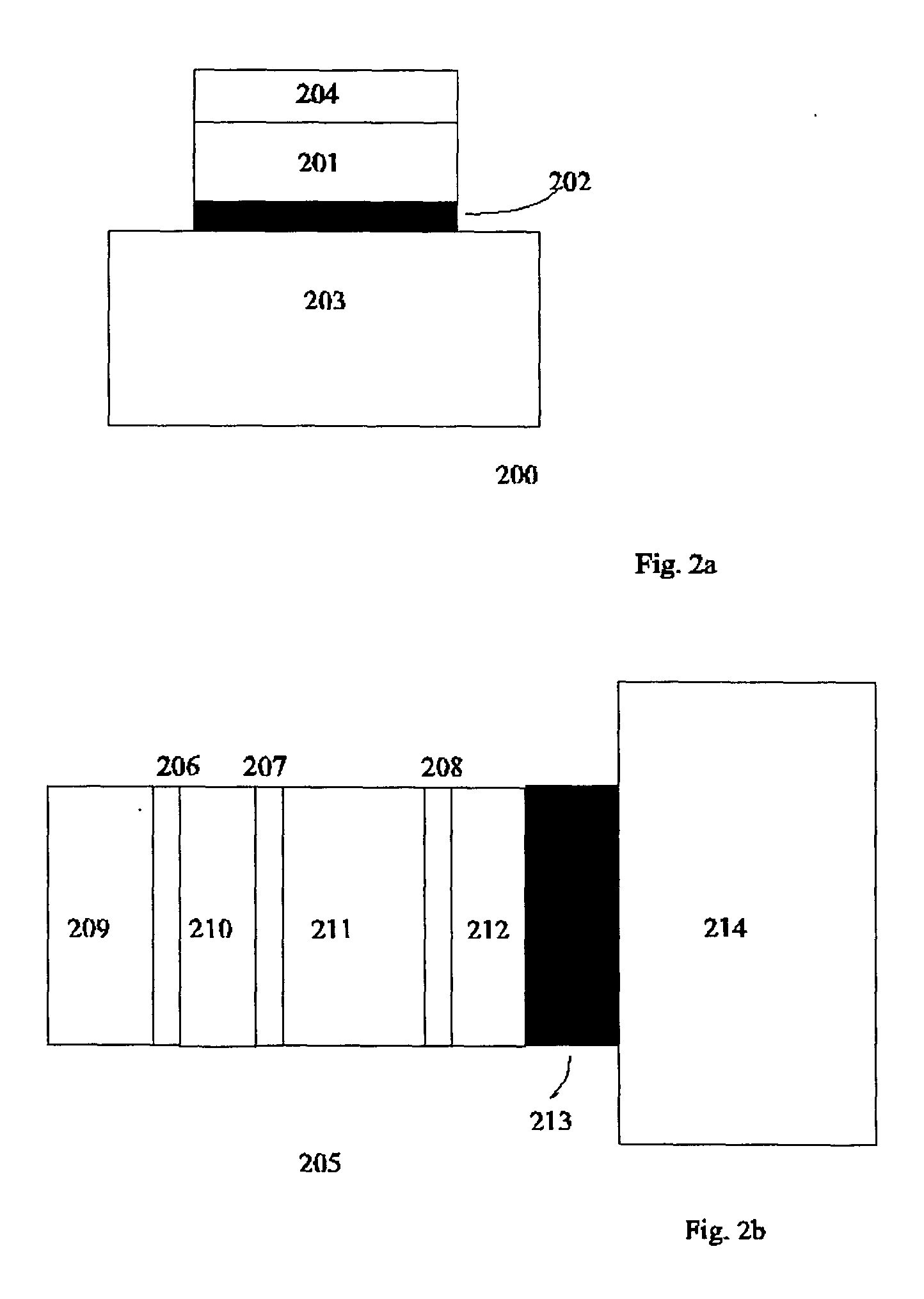
[0025] In aluminum containing semiconductors the surface area can induce a low optical damage threshold triggered by oxidization of the surface. In order to prevent optical damage of aluminum containing surface areas a
passivation layer, e.g., InP, InGaAs or GaAs, is incorporated. SA degradation is further minimized by optimizing the
optical beam diameter that impinges on the SAM. In one implementation the SAM and an intra-cavity fiber end can be either butt-coupled or brought into
close contact to induce modelocking. Here, the incorporation of a precision AR-
coating on the intra-cavity fiber end minimizes any bandwidth restrictions from etalon formation between the SAM and the fiber end. Etalons can also be minimized by appropriate wedging of the fiber ends. The
beam diameter inside the SAM can be adjusted by implementing fiber ends with thermally expanded cores. Alternatively, focusing lenses can be directly fused to the fiber end. Moreover, graded-index lenses can be used for optimization of the focal size and working distance between the fiber tip and SA surface.
[0027] The use of bi-or multi-temporal saturable absorbers allows the design of dispersion compensated fiber laser operating in a single-polarization state, producing pulses at the bandwidth limit of the fiber
gain medium. Additional spectral broadening can be obtained by launching these pulses into highly nonlinear fibers, allowing for the generation of broad-bandwidth pulses with bandwidths exceeding one
octave for use in
optical coherence tomography or in precision
metrology.

