

Polymer based lanthanide luminescent sensors for the detection of organophosphorus compounds
a technology of luminescent sensors and lanthanide, which is applied in the direction of fluorescence/phosphorescence, instruments, laboratory glassware, etc., can solve the problems of few small and inexpensive sensors with the capability to do real-time monitoring/detecting, and the documented environmental pollution
- Summary
- Abstract
- Description
- Claims
- Application Information
AI Technical Summary
Benefits of technology
Problems solved by technology
Method used
Image

Examples
example 1
Compound Preparation
[0094] Lanthamide complex compounds were synthesized using a stoichiometric ratio of one mole of europium to one mole of PMP and 3 to 7 moles of ligating molecules. (The number of ligating species depended on the number of ligands needed to acquire 9 coordinate Eu 3+.) The calculated amount of each ligand was added to the europium solutions. PMP was added to a 50 / 50 water-methanol mixture to enhance its solubility, then added to the europium / ligand mixture. The resulting solutions were stirred approximately 2 hours, then left to evaporate the solvent. Analogous compounds without PMP were also synthesized. Eu(DVMB)3PMP(NO3)2 and Eu(DVMB)3(NO3)3 were synthesized in the manner detailed above. (Divinyl methyl benzoate (DVMB) was freshly prepared.:before use since it readily polymerizes.) Shea, K. J., et al., Macromolecules, 24:1207-1209(1991). The stoichiometry of Eu(DVMB)3PMP(N3)2 was verified using ICP-MS Eu 16.12% (calculated 16.36%). Low temperature crystal spec...
example 2
Polymer Preparation
[0095] Styrenic block copolymers were prepared and the optimal mole percent complex for the preparation of the polymer coating determined. Polymers were prepared by dissolving 1 to 5 mole percent complex compound in 94-98 mole percent styrene. Approximately 1 mole percent of azobisisobutylnitrile (AIBN) was added as an initiator to the mixture described in Example 1. Crosslinked polymers were also prepared using 3 mole percent compound with 1-5 mole percent of a crosslinking agent divinyl benzene (DVB), styrene and AIBN. The resulting solutions were placed in glass vials, purged with nitrogen, and sealed using parafilm and screw on tops. The resulting translucent polymers displayed a slight yellow tint and upon excitation with a uv lamp, displaying the characteristic red-orange luminescence of curopium. The best results were obtained front the 3 mole percent complex. The 610 nm peak was intense and easily discernible from other Eu(III) peaks. Lower percent comple...
example 3
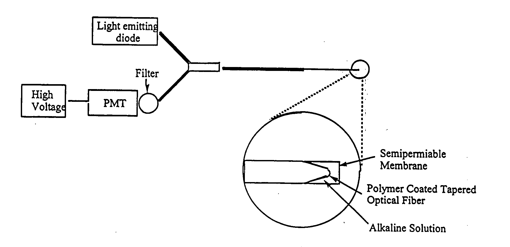
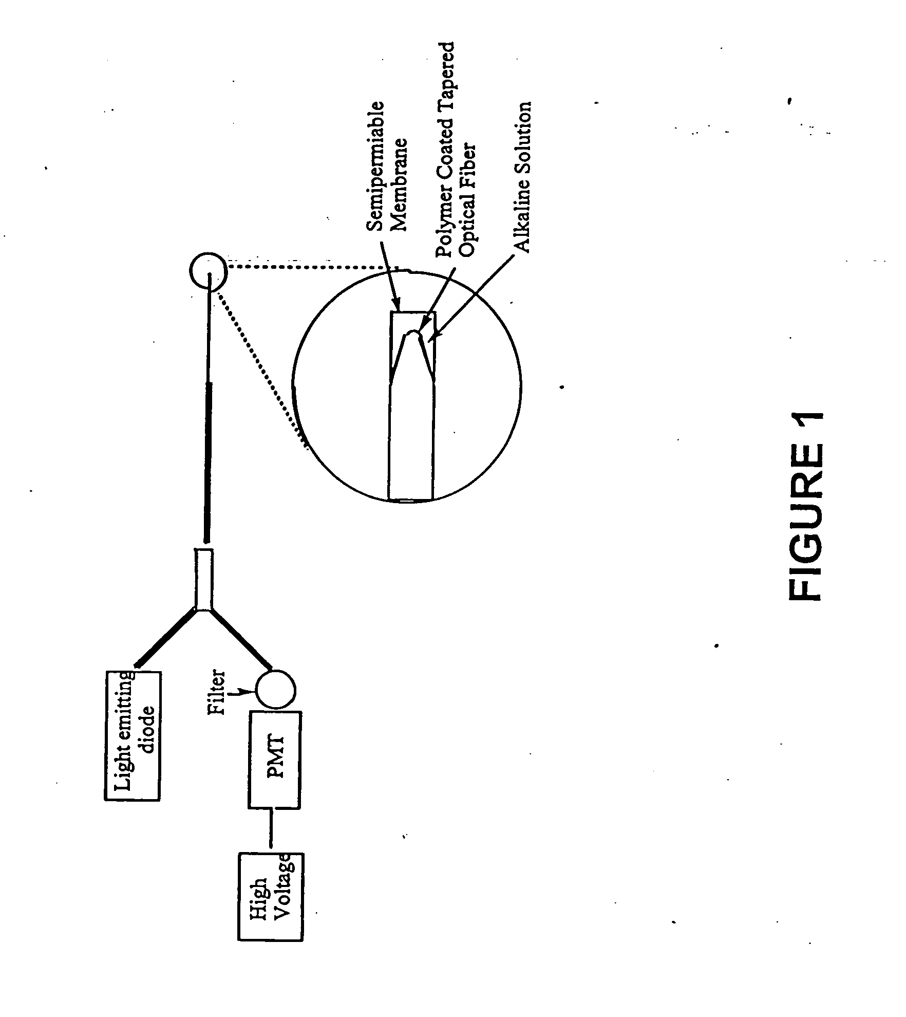
[0098] A fiber optic sensor comprising a 400 micron optical fiber (Thor Labs, Newton, N.J., 07860) with the polymeric sensing element chemically bound on its distal end was constructed. The fibers were prepared by terminating one end with an SMA connector and removing the cladding from and polishing the distal end using the procedures outlined in the “Thor Labs Guide to Connectorization and Polishing of Optical Fibers”. The tips were dipped into the chemically initiated viscous copolymer described in Example 2 leaving a uniform layer on the fiber. The polymer finished curing under a small UV lamp, overnight. Coated fibers were conditioned in a manner similar to the ground polymers as outlined above. Final versions of the sensor were prepared using a tapered fiber created by heating it in an air / acetylene flame and manually pulling the stripped end. The tapered fibers were much more efficient at coupling the evanescent field to the polymer and gave greatly improved...
PUM
| Property | Measurement | Unit |
|---|---|---|
| Permeability | aaaaa | aaaaa |
| Energy | aaaaa | aaaaa |
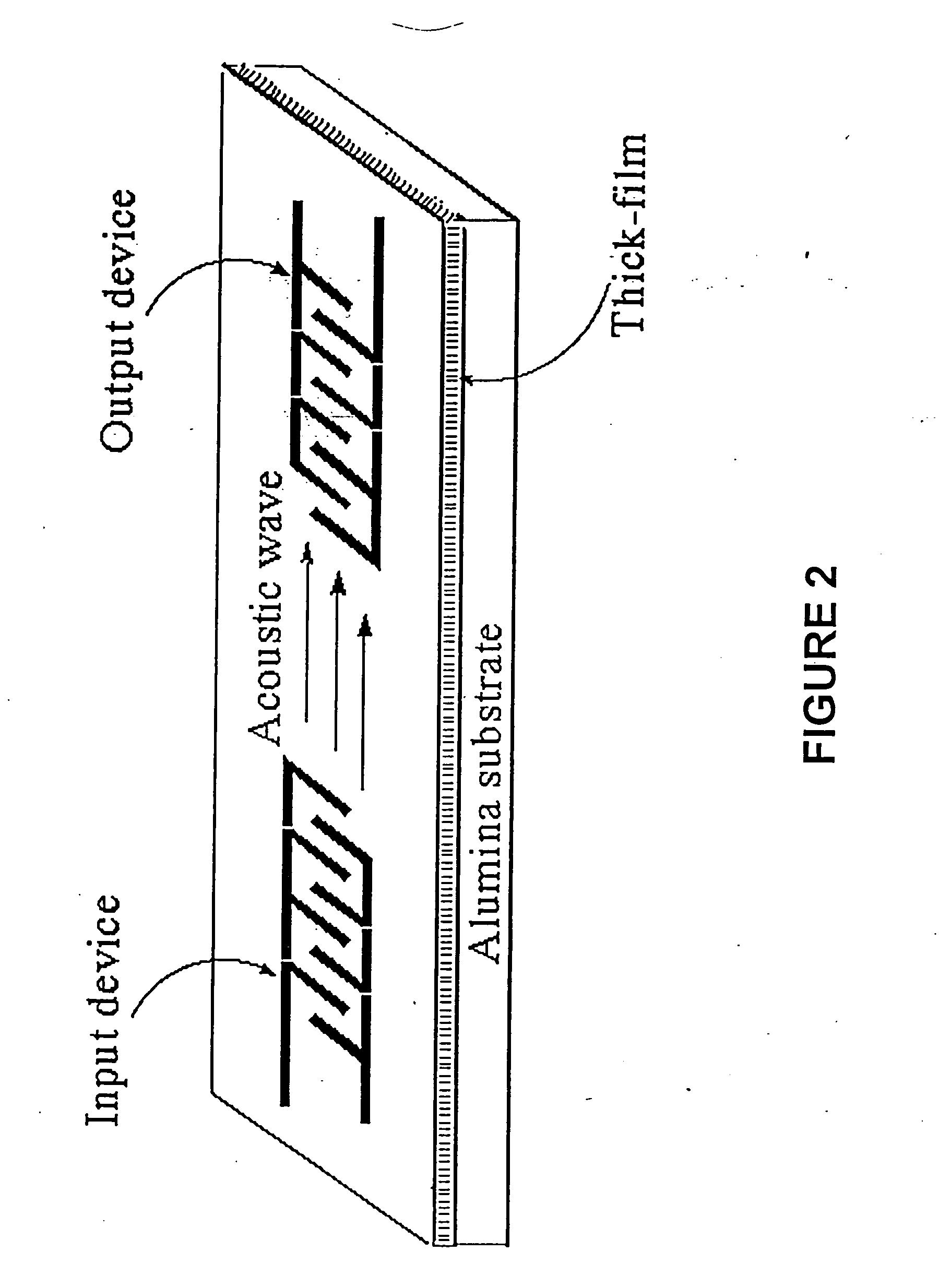
| Surface acoustic wave | aaaaa | aaaaa |
Abstract
Description
Claims
Application Information