Copper foil for high frequency circuit, method of production and apparatus for production of same, and high frequency circuit using copper foil

a high-frequency circuit and copper foil technology, applied in the field of copper foil, can solve problems such as dielectric loss, drop in bond strength of copper foil and circuit board, increase in transmission loss due to conductor loss and bond strength drop, etc., and achieve excellent bond strength and reduce transmission loss

Inactive Publication Date: 2005-01-27
FURUKAWA ELECTRIC CO LTD
View PDF11 Cites 9 Cited by
  • Summary
  • Abstract
  • Description
  • Claims
  • Application Information

AI Technical Summary

Benefits of technology

An object of the present invention is to provide a copper foil reducing transmission loss at a high frequency when used as a material for a high frequency circuit and excellent in bond strength with a resin substrate, a method of production and apparatus for production for the same, and a high frequency circuit using the same.

Problems solved by technology

If viewing the transmission loss from the perspective of the copper foil forming the base of the conductor circuits, the increase in transmission loss due to conductor loss and the drop in bond strength with the resin accompanying the reduction in dielectric constant and reduction in dielectric dissipation factor of the substrate in order to keep down the dielectric loss (drop in bond strength of copper foil and circuit board) become problems.
If the signal becomes high in frequency, the loss is increased due to the increase in the skin resistance.
At a high frequency, the skin effect (where passage of an alternating current through the conductor results in a change in the magnetic flux and therefore the occurrence of an inverse electromotive force at the center of the conductor and a consequent difficulty in flow in current) means that the current will flow at the surface portion of the conductor.
Therefore, the profile of the copper foil at the surface has a great effect on the transmission loss.
A very rough copper foil has a longer signal propagation distance, resulting in problems of signal attenuation or delay.
When the period (frequency) of change of the electric field approaches the relaxation time of polarization of the resin, a delay will be caused in the electric displacement.
This heat will result in dielectric loss.
A resin reduced in substituent groups with a large polarity so as to reduce the dielectric constant and dielectric dissipation factor becomes poor in bondability with copper foil resulting in a sharp drop in the peel strength of the circuit.
The generally used FR-4 material gives a high peel strength due to cohesion destruction (in the resin), but with low dielectric dissipation factor substrates, interfacial destruction (interface of copper foil and resin) occurs and a high peel strength cannot be obtained.
With such a low peel strength, there is a possibility of circuit peeling or mounted parts dropping off at the outermost layer in the process of production of a printed circuit board.
The problem of the peel strength can be circumvented by use of a copper foil with a large roughness, but in high frequency applications, as explained above, the transmission loss would become greater, so use would become difficult.
That is, a good peel strength and transmission loss are properties difficult to secure at the same time.
However, while the high strength, high conductivity copper alloys in use now as lead frame materials have a higher material strength compared with pure copper foil, they are becoming insufficient for coping with the demands of recent years for higher speed signal transmission, smaller size, and greater reliability.
Use of copper alloys improved in properties compared with conventional copper alloys is being proposed to deal with the demands for fine pitches and lighter weight (for example, see Japanese Unexamined Patent Publication (Kokai) No. 2002-167633), but none of these has satisfied the requirements of an antenna material of sufficient bond strength with a resin and reduced transmission loss in the high frequency region.

Method used

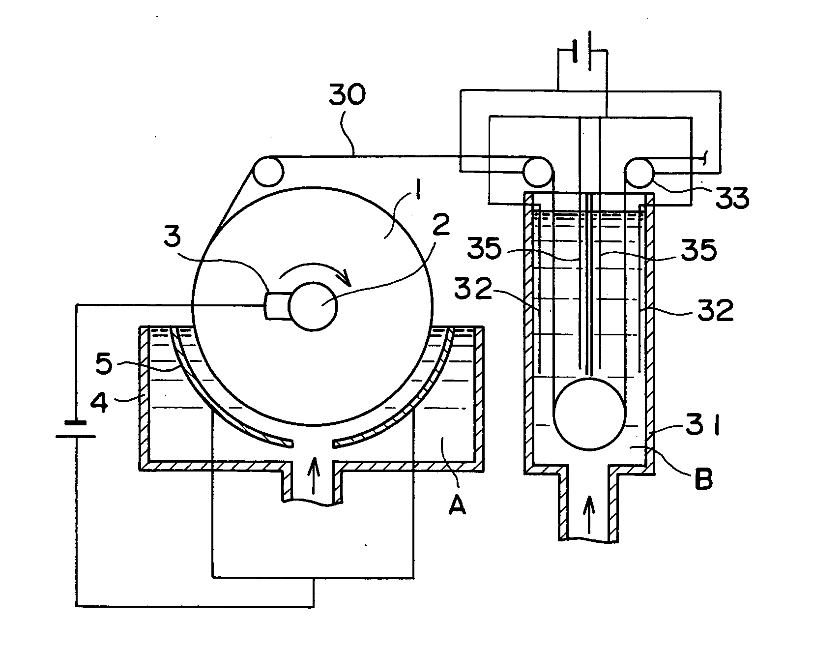
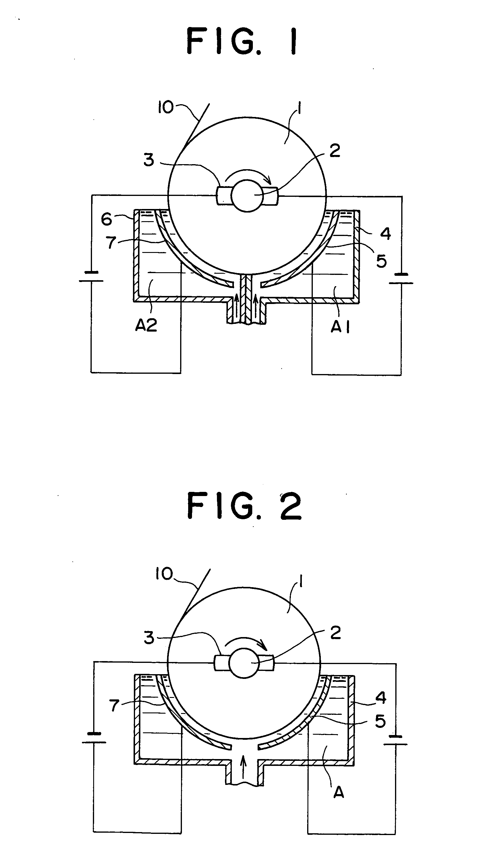
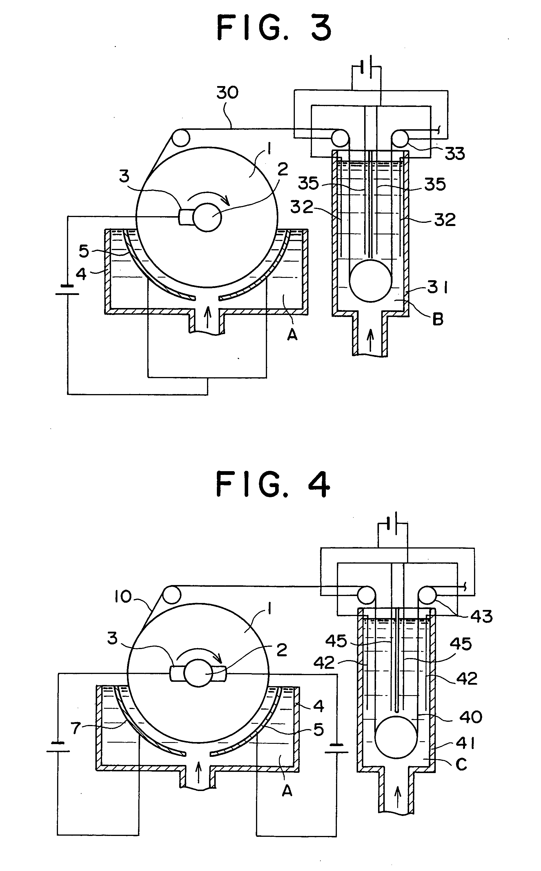

Image

  • Copper foil for high frequency circuit, method of production and apparatus for production of same, and high frequency circuit using copper foil
  • Copper foil for high frequency circuit, method of production and apparatus for production of same, and high frequency circuit using copper foil
  • Copper foil for high frequency circuit, method of production and apparatus for production of same, and high frequency circuit using copper foil

Examples


example 1

Using a titanium electrolytic drum polished smoothly by #2000 buff as a cathode, a 28 μm copper foil was prepared by granular layer plating. The copper foil was peeled off from the titanium electrolytic drum, then a 2 μm columnar layer was plated on its shiny side, that is, granular surface which had been in contact with titanium electrolytic drum (granular layer: about 93%). This was then further nickel plated, zinc plated, chromate treated, then treated by a silane coupling agent.

example 2

In the same way as in Example 1, a 26 μm copper foil was prepared by granular layer plating, peeled off from the titanium electrolytic drum, plated on its shiny side with a 4 μm columnar layer (granular layer: about 87%), then further nickel plated, zinc plated, chromate treated, then treated by a silane coupling agent.

example 3

In the same way as in Example 1, a 24 μm copper foil was prepared by granular layer plating, peeled off from the titanium electrolytic drum, plated on its shiny side with a 6 μm columnar layer (granular layer: about 80%), then further nickel plated, zinc plated, chromate treated, then treated by a silane coupling agent.


PUM

PropertyMeasurementUnit
roughnessaaaaaaaaaa
roughnessaaaaaaaaaa
roughnessaaaaaaaaaa

Abstract

A copper foil reducing transmission loss at a high frequency and excellent in bond strength with a resin substrate, including at least a granular layer and a columnar layer in its thickness direction, the columnar layer being formed on at least one surface of the granular layer forming the copper foil or the granular layer being formed on at least one surface of the columnar layer forming the copper foil, the relation of the thickness A of the granular layer and the thickness B of the columnar layer in the copper foil being preferably A/(A+B)=40 to 99%, a method of production and apparatus for production for the same, and a high frequency circuit using the same.

Description

BACKGROUND OF THE INVENTION 1. Field of the Invention The present invention relates to a copper foil reducing conductor loss in high frequency applications and superior in bond strength with a substrate, more particularly a copper foil superior for use in a high frequency circuit, for example, relates to a copper foil optimal for a high frequency circuit including an antenna of an IC card; a method of production and apparatus for production for the copper foil; and a high frequency circuit using that copper foil. 2. Description of the Related Art As the resin of a substrate of a printed circuit board handling a high frequency signal, a polyimide resin, modified polyimide resin, fluororesin, polystyrene, polyethylene, polyphenylene sulfide, polyphenyloxide, polytetrafluoroethylene, etc. is used. For the conductor circuits, normally copper foil is used since its conductivity is high and it is resistant to stain. A printed circuit board for a high frequency circuit has to be reduc...

Claims


Application Information

Patent Timeline
Patent Type & Authority Applications(United States)
IPC IPC(8): C25D1/04C25D7/06H05K1/02H05K1/09
CPCC25D1/04C25D7/0614H05K1/0237H05K1/09Y10S428/935Y10T428/12569Y10T428/12431Y10T428/1291Y10T428/12438H05K2201/0355
Inventor MOTEKI, TAKAMISUZUKI, YUUJIHOSHINO, KAZUHIROSHINOZAKI, KENSAKUMATSUDA, AKIRA
Owner FURUKAWA ELECTRIC CO LTD
Why Eureka
Try Eureka