
Separator for fuel cell and fuel cell using the same

a fuel cell and separator technology, applied in the direction of cell components, electrochemical generators, cell component details, etc., can solve the problems of increasing the number of steps and the cost, difficult to make conventional separators thinner, and difficult to form thin fuel cells, so as to achieve convenient manufacturing and maintenance, maintain strength, and reduce the number of steps.

Inactive Publication Date: 2005-02-03
NITTO DENKO CORP
View PDF4 Cites 50 Cited by
  • Summary
  • Abstract
  • Description
  • Claims
  • Application Information

AI Technical Summary

Benefits of technology

The present invention has been made in view of the above-mentioned situation, wherein the object is provision of a separator for a fuel cell, which is lightweight and easily made thin, and which has superior corrosion resistance and shape stability and a fuel cell using the separator.
The separator for fuel cell of the present invention has a structure wherein a conductive layer containing an electroconductive material (metal material) is partially formed on both principal planes of a substrate (insulation layer). Therefore, it can be easily made thin and lightweight, has flexibility, maintains strength even when made comparatively thin, and has superior shape stability. These are superior characteristics absent in conventional separators. Accordingly, effects such as realization of a lightweight fuel cell (fuel cell stack) thinner than conventional ones and improved vibration resistance, durability and the like of the cell can be afforded by the use of the separator.
In addition, a fuel cell (the fuel cell assembly structure of the present invention) wherein an electricity generating element assembly obtained by forming plural electricity generation membrane electrode composite structures on a single electrolyte membrane is supported by being sandwiched between the separator assemblies for fuel cell of the present invention from both surfaces of top and bottom thereof is thin and high power as well.

Problems solved by technology

However, it is difficult to make conventional separators thinner.
As a result, conventional fuel cells thicken naturally, which particularly makes it difficult to form a thin fuel cell.
However, since a separator with the use of a metal plate not only becomes heavier but is associated with the defects in that it is deteriorated by a long term contact with a hydrogen gas to be used as a fuel gas, cutting work and etching processing for groove formation are needed, thus increasing the number of steps and the cost, and when it is made thin, plastic deformation occurs, thus making shape retention difficult.
In contrast, while a graphite plate is superior in gas impermeability and lightweight, it is expensive and requires a long time for the production of the graphite plate itself.
Therefore, it is inferior in the productivity.
Moreover, since processing of graphite plate requires slice cutting with a diamond cutter, the number of steps and the cost increase.
Moreover, since a graphite plate has a high hardness, it easily gets broken when made thin.

Method used


Image

  • Separator for fuel cell and fuel cell using the same
  • Separator for fuel cell and fuel cell using the same
  • Separator for fuel cell and fuel cell using the same

Examples


example 1

(Preparation of Separator)

A laminate plate comprising copper layers each having a thickness of 0.018 mm laminated on both principal planes of a glass epoxy substrate having a thickness of 1.6 mm was prepared and holes having a diameter of 1 mm were formed with a drill at predetermined positions in the principal plane of the laminate plate. Then, copper plating was applied to the entire surfaces of the both surfaces of the laminate plate until the copper layer came to have a thickness of 0.2 mm. As a result, a via hole having a copper layer formed on the inner surface of the holes having a diameter of 1 mm was obtained. The copper layer on the inner surface of the holes having a diameter of 1 mm was linked to the copper layer laminated on the principal plane of the laminate plate. Then, a through-hole remaining inside the copper layer in the via hole was filled with a liquid epoxy resin (EPOX-AH333, Mitsui Chemical) and cured to seal the hole. A dry film resist (SPG-252, Asahi Kas...

example 2

(Preparation of Separator)

A laminate plate comprising copper layers each having a thickness of 0.018 mm laminated on both principal planes of a glass epoxy substrate having a thickness of 1.6 mm was prepared and holes having a diameter of 1 mm were formed with a drill at predetermined positions in the principal plane of the laminate plate. Then, copper plating was applied to the entire surfaces of the both surfaces of the laminate plate until the copper layer came to have a thickness of 0.03 mm. As a result, a via hole having a copper layer formed on the inner surface of the holes having a diameter of 1 mm was obtained. The copper layer on the inner surface of the holes having a diameter of 1 mm was linked to the copper layer laminated on the principal plane of the laminate plate. Then, a through-hole remaining inside the copper layer in the via hole was filled with a liquid epoxy resin (EPOX-AH333, Mitsui Chemical) and cured to seal the hole. The both principal planes of a glass...

example 3

(Preparation of Fuel Electrode and Oxygen Electrode)

A paste comprising a polymer electrolyte membrane (“Nafion”, DuPont) solution, a carbon powder and a platinum catalyst (Nafion:carbon powder:platinum catalyst=7:5:3 (weight ratio)) was prepared. This paste was applied onto a carbon paper (thickness 175 μm) with a bar coater and dried at 80° C. for 5 min to form a paste membrane on the carbon paper, which was then subjected to a heat press (130° C., 2 min, 20 kgf / cm2) to smooth the surface of the paste membrane (dry thickness 50 μm). Two sheets of carbon paper having a smooth surface and a paste membrane were formed and used as a fuel electrode and an oxygen electrode as in the following.

(Preparation of Fuel Cell Stack)

A polymer electrolyte membrane (“Nafion N-112”, DuPont, thickness 50 μm) was sandwiched between the aforementioned fuel electrode and the oxygen electrode such that a catalyst surface (paste surface) of the electrodes was in contact with the polymer electrolyte...


PUM

PropertyMeasurementUnit
thicknessaaaaaaaaaa
thicknessaaaaaaaaaa
thicknessaaaaaaaaaa

Abstract

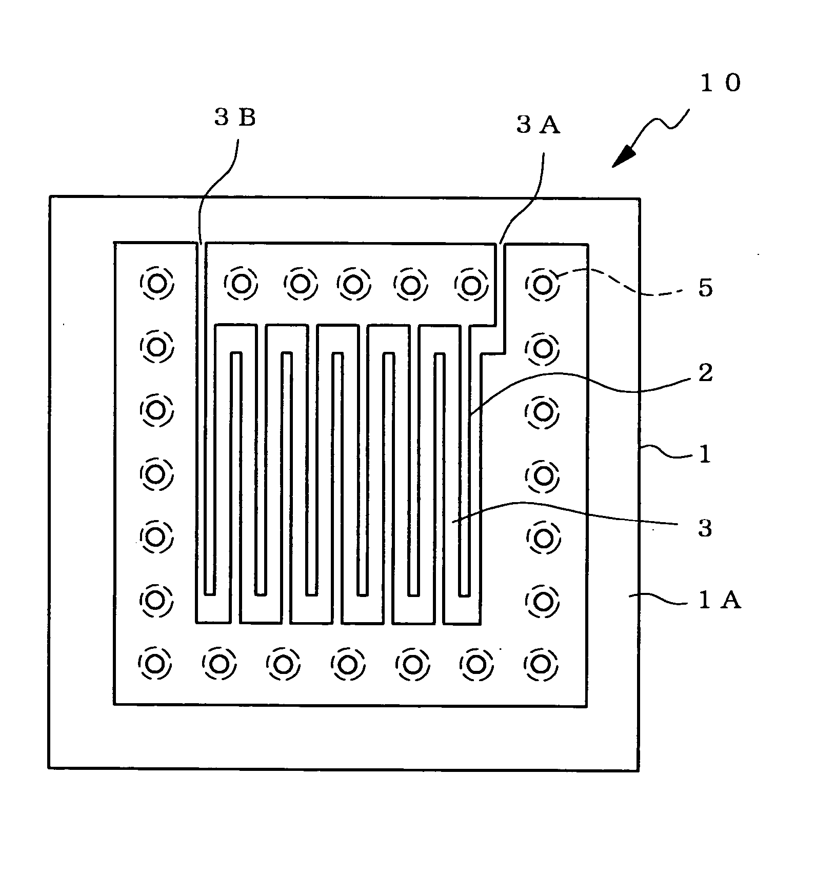
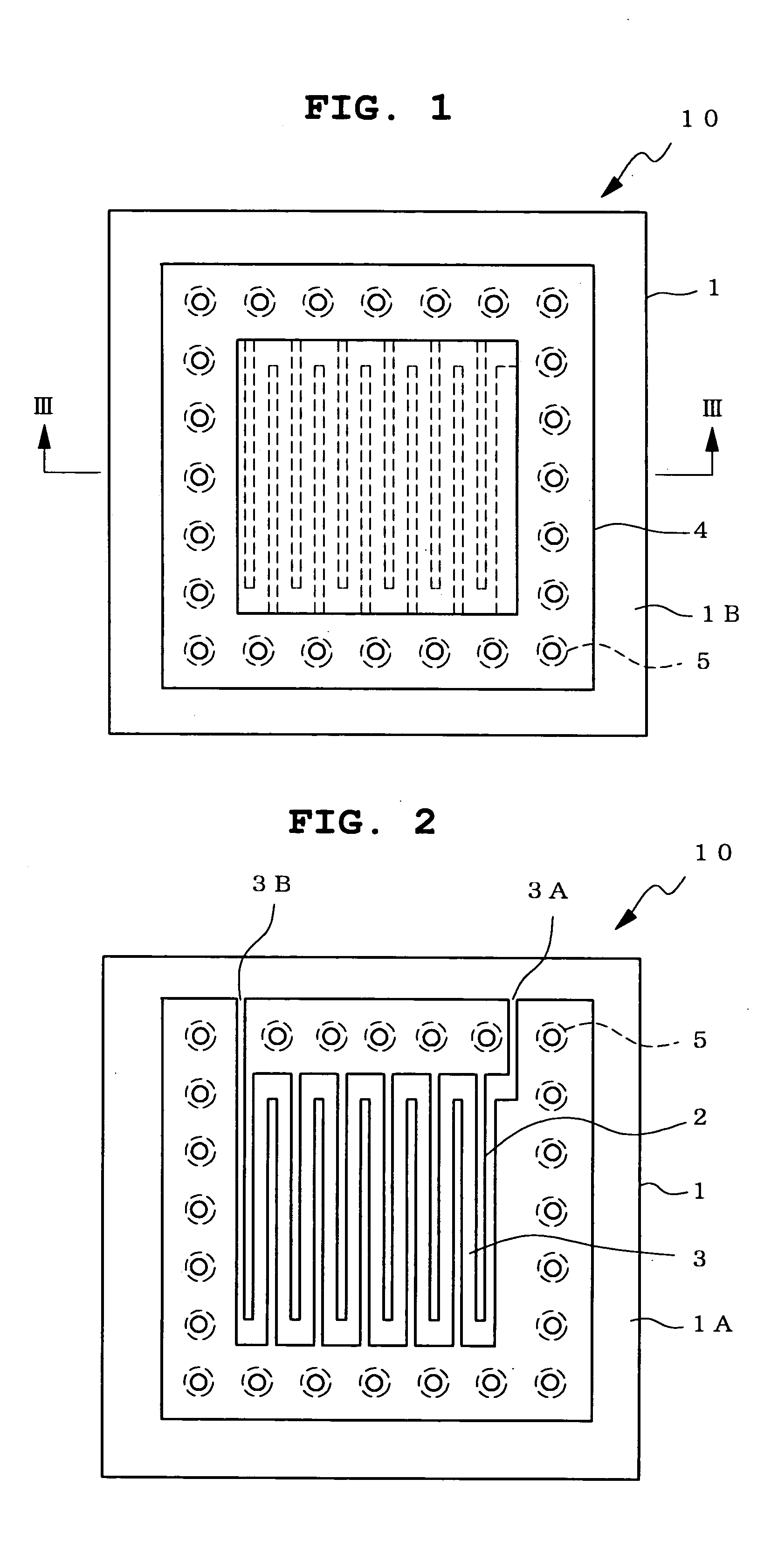
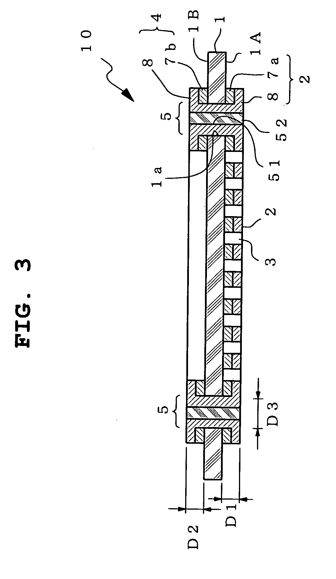
The present invention provides, as a separator for fuel cell which is lightweight, can be easily made thin, and which has superior corrosion resistance and shape stability, a fuel cell 100 containing a separator for fuel cell 10, wherein a conductor pattern 2 is formed on one principal plane 1A of an insulation layer 1 to form a groove for a gas flow path 3 sectioned by the conductor pattern 2 on this principal plane, a conductor terminal 4 is formed on the other principal plane 1B of the insulation layer 1, and this conductor terminal 4 and the conductor pattern 2 are electrically connected by a via hole 5 penetrating the insulation layer 1, and a membrane electrode assembly (complex having an electrolyte membrane and an electrode (fuel electrode, oxygen electrode) laminated thereon) 14 having the separator for fuel cell disposed on both surfaces.

Description

FIELD OF THE INVENTION The present invention relates to a separator for a fuel cell, which is easy to be made thin and is lightweight, a fuel cell using the separator, a wiring circuit board with the separator for fuel cell and a fuel cell built-in wiring circuit board. BACKGROUND OF THE INVENTION As an energy source that does not cause environmental pollution, a fuel cell is attracting attention and researches thereof are actively done in recent years. A fuel cell directly generates electricity by electrochemically reacting hydrogen and oxygen. A fuel cell is basically composed of, as a unit, a power generation cell wherein a membrane electrode assembly is held by being sandwiched between a separator having a groove to be a flow path of a fuel gas (hydrogen gas) and a separator comprising groove to be a flow path of oxygen (air) gas. Here, the membrane electrode assembly consists of an electrolyte membrane, a fuel electrode arranged on one surface of the electrolyte membrane, and...

Claims


Application Information

Patent Timeline
Patent Type & Authority Applications(United States)
IPC IPC(8): H01M8/02H01M8/10H01M8/24
CPCH01M8/0206H01M8/0228Y02E60/50H01M8/242H01M8/0256H01M8/2418
Inventor OUCHI, KAZUOISHIZAKA, HITOSHI
Owner NITTO DENKO CORP
Learn More