
Position location and data transmission using pseudo digital television transmitters

Inactive Publication Date: 2005-02-10
TRUE POSITION INC
View PDF30 Cites 37 Cited by
  • Summary
  • Abstract
  • Description
  • Claims
  • Application Information

AI Technical Summary

Benefits of technology

The signals disclosed herein have several advantages for acquisition and tracking over the conventional ATSC DTV signal. Initial acquisition can be performed with a search over 832 symbols as in the symbol synchronization search. A matched filter can be used with the full 832-symbol length instead of simply looking for the 4-symbol segment sync code, producing a much higher initial synchronization processing gain. Furthermore, this acquisition takes only 77 microseconds and is very tolerant of Doppler offset.
The second search is over the 313 segments that make up the c313 code described below, and can also be performed with a matched filter processing the matched filter peaks from the 832-chip code. Thus the acquisition time is greatly reduced over that of a single long 313×832 chip code and performs quite well. The acquisition of the 313-chip code then allows the half field synchronization, providing the full processing gain, and recovery of any data stream in the signal.
The DTV signal has a power advantage over GPS of more than 40 dB, and substantially superior geometry to that which a satellite system could provide, thereby permitting position location even in the presence of blockage and indoors. The DTV signal has roughly six times the bandwidth of GPS, thereby minimizing the effects of multipath. Due to the high power and low duty factor of the DTV signal used for ranging, the processing requirements are minimal. Implementations of the present invention accommodate far cheaper, lower-speed, and lower-power devices than a GPS technique would require.
In contrast to satellite systems such as GPS, the range between the DTV transmitters and the user terminals changes very slowly. Therefore the DTV signal is not significantly affected by Doppler effects. This permits the signal to be integrated for a long period of time, resulting in very efficient signal acquisition.
The frequency of the DTV signal is substantially lower that that of conventional cellular telephone systems, and so has better propagation characteristics. For example, the DTV signal experiences greater diffraction than cellular signals, and so is less affected by hills and has a larger horizon. Also, the signal has better propagations characteristics through buildings and automobiles.
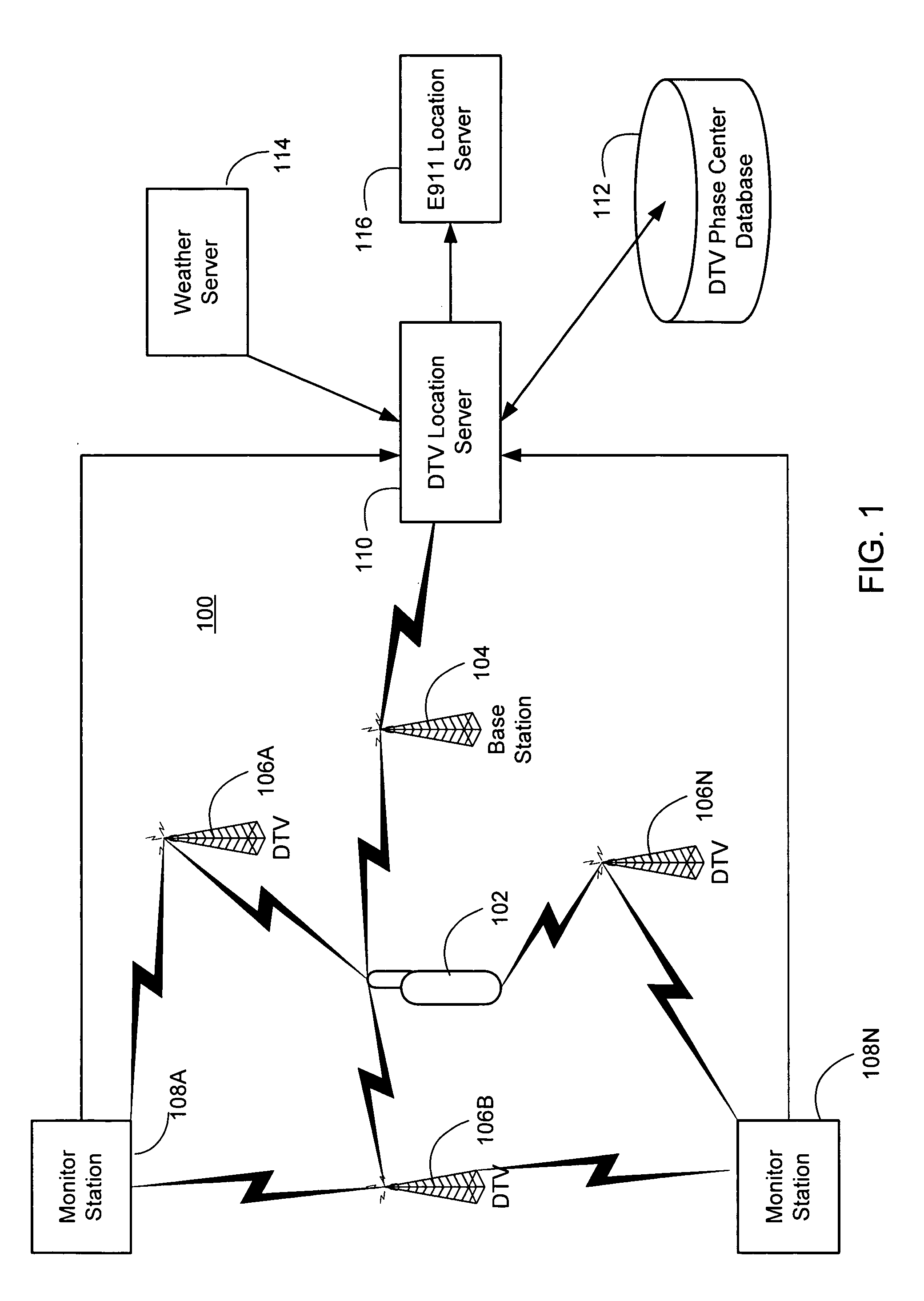
Unlike the terrestrial Angle-of-Arrival / Time-of-Arrival positioning systems for cellular telephones, implementations of the present invention require no change to the hardware of the cellular base station, and can achieve positioning accuracies on the order of 1 meter. When used to position cellular phones, the technique is independent of the air interface, whether GSM (global system mobile), AMPS (advanced mobile phone service), TDMA (time-division multiple access), CDMA, or the like. A wide range of UHF (ultra-high frequency) frequencies has been allocated to DTV transmitters. Consequently, there is redundancy built into the system that protects against deep fades on particular frequencies due to absorption, multipath and other attenuating effects.

Problems solved by technology

However in some situations, GPS is less effective.
Thus the signal is marginally useful or not useful at all in the presence of blockage or inside a building.
However, the same problems of signal level and coverage apply to GPS pseudo-lites.

Method used


Image

  • Position location and data transmission using pseudo digital television transmitters
  • Position location and data transmission using pseudo digital television transmitters
  • Position location and data transmission using pseudo digital television transmitters

Examples


Embodiment Construction

Introduction

Digital television (DTV) is growing in popularity. DTV was first implemented in the United States in 1998. As of the end of 2000, 167 stations were on the air broadcasting the DTV signal. As of Feb. 28 2001, approximately 1200 DTV construction permits had been acted on by the FCC. According to the FCC's objective, all television transmission will soon be digital, and analog signals will be eliminated. Over 1600 DTV transmitters are expected in the United States.

These new DTV signals permit multiple standard definition TV signals or even high definition signals to be transmitted in the assigned 6 MHz channel. These new American Television Standards Committee (ATSC) DTV signals are completely different from the analog NTSC TV signals, are transmitted on new 6 MHz frequency channels, and have completely new capabilities.

The inventors have recognized that the ATSC signal can be used for position location, and have developed techniques for doing so. These techniques ar...


PUM


Abstract

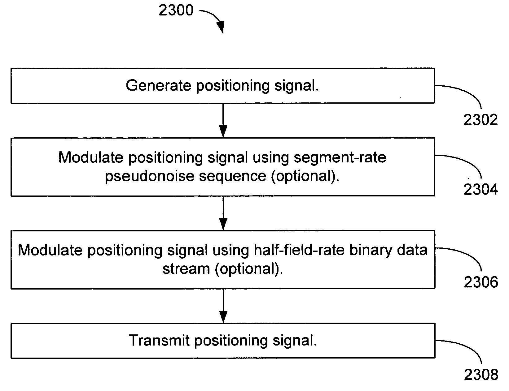
A method, apparatus, and computer-readable media comprising generating a positioning signal comprising a first half-field and a second half-field; and transmitting the positioning signal; wherein each of the first and second half-fields comprises 313 segments; and wherein each of the segments comprises 832 chips comprising an American Television Standards Committee (ATSC) digital television (DTV) segment synchronization signal and a pseudonoise sequence.

Description

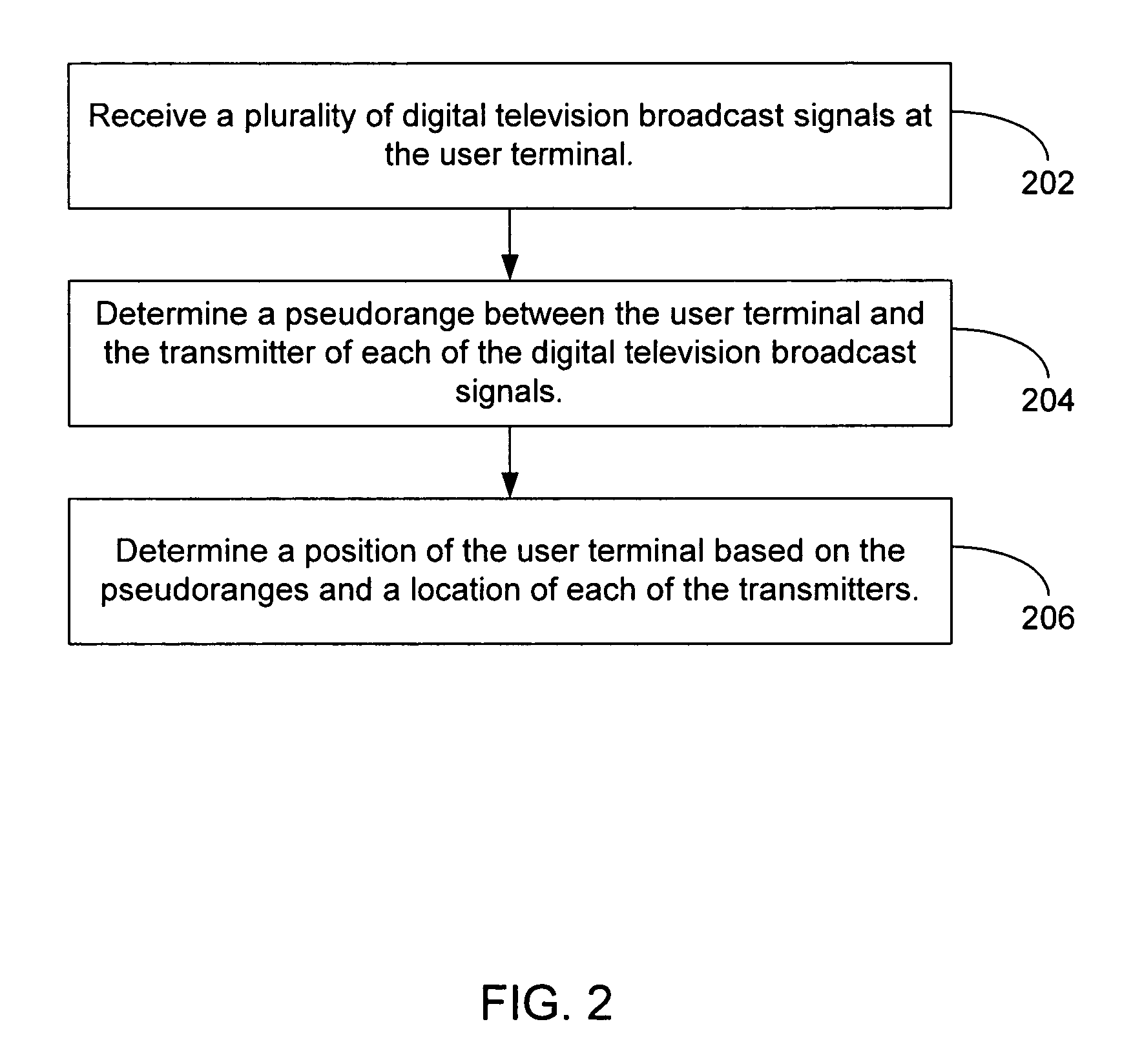
BACKGROUND The present invention relates generally to data transmission, and particularly to position location and data transmission using pseudo digital television transmitters. There have long been methods of two-dimensional latitude / longitude position location systems using radio signals. In wide usage have been terrestrial systems such as Loran C and Omega, and a satellite-based system known as Transit. Another satellite-based system enjoying increased popularity is the Global Positioning System (GPS). Initially devised in 1974, GPS is widely used for position location, navigation, survey, and time transfer. The GPS system is based on a constellation of 24 on-orbit satellites in sub-synchronous 12 hour orbits. Each satellite carries a precision clock and transmits a pseudo-noise signal, which can be precisely tracked to determine pseudo-range. By tracking 4 or more satellites, one can determine precise position in three dimensions in real time, world-wide. More details are pr...

Claims


Application Information

Patent Timeline
IPC IPC(8): G01S3/02G01S19/46H01Q3/00
CPCG01S5/0036G01S5/145G01S5/0226G01S5/021
Inventor SPILKER, JAMES J. JR.
Owner TRUE POSITION INC
Learn More