
Atmospheric corrosion sensor

a sensor and atmosphere technology, applied in the field of atmospheric corrosion sensors, can solve the problems of short circuit between the two electrodes, and release of metallic ions by corrosion of one electrode into the electrolyte, and achieve the effect of promoting corrosion of metallic objects and low cos

Active Publication Date: 2005-02-17
ZAMANZADEH MEHROOZ +1
View PDF6 Cites 27 Cited by
  • Summary
  • Abstract
  • Description
  • Claims
  • Application Information

AI Technical Summary

Benefits of technology

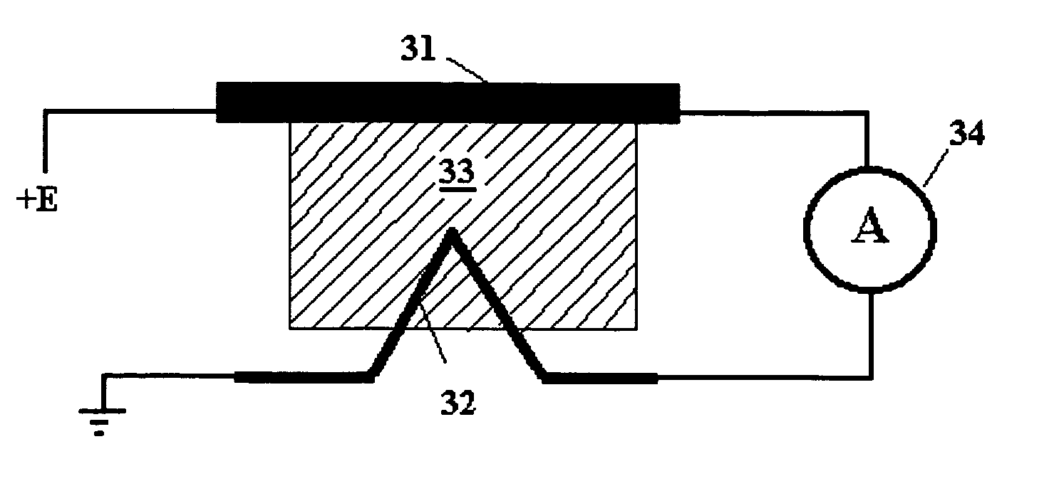
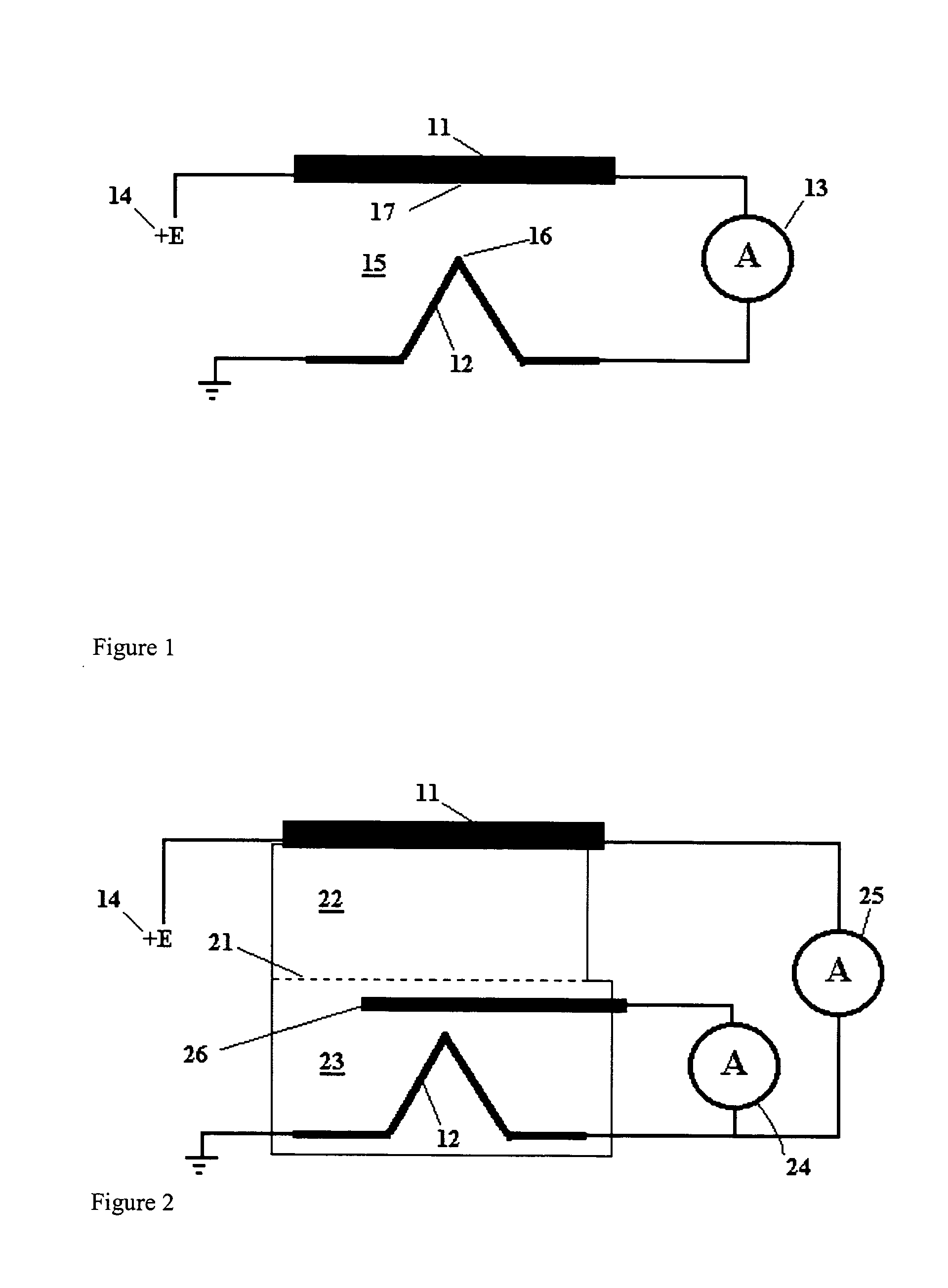
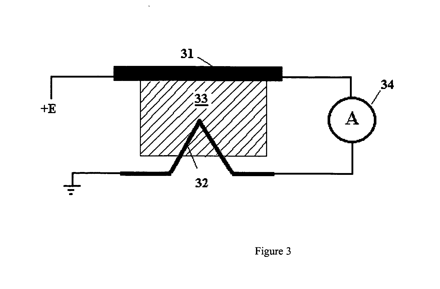
"The present invention provides a low cost sensor for monitoring the local atmosphere for its propensity for promoting corrosion of metallic objects. The sensor consists of two or more closely spaced metal electrodes on a substrate electrical connected via an electrolyte, with a constant electrical potential applied between them. When exposed to a corrosive gas, corrosion of one of the electrodes releases metallic ions into the electrolyte. These ions migrate to the opposing electrode whereupon they are reduced back to the metal. The metal forms a metal bridge eventually resulting in a short circuit between the two electrodes. The corrosion tendency of the atmosphere is measured by both an instantaneous measurement of the current flowing between the two electrodes and by the time taken for the deposited metal to bridge the two electrodes. The sensor can detect the formation of a conductive bridge between the electrodes, which indicates the cumulative exposure of the sensor to the corrosive gases. The sensor can also produce an alternating current that can be used to measure the conductivity of the sensor, which can be used to detect the formation of the conductive bridge between the electrodes. The electrodes can be selected so as to produce a galvanic cell within the sensor, which would allow the sensor to operate without external power being applied."

Problems solved by technology

In the presence of a corrosive gas, corrosion of one of the electrodes releases metallic ions into the electrolyte.
Upon prolonged exposure to the corrosive gas, the deposited metal forms a metal bridge eventually resulting in a short circuit between the two electrodes.

Method used


Image

  • Atmospheric corrosion sensor
  • Atmospheric corrosion sensor
  • Atmospheric corrosion sensor

Examples


Embodiment Construction

As described in above there is a great need for an efficient and economical system for monitoring for the presence of corrosive gases. The most common corrosive gases encountered are sulfur dioxide (SO2), hydrogen sulfide (H2S), nitric oxide (NO), nitrogen dioxide / dinitrogen tetroxide (NO2 / N2O4) and hydrogen chloride (HCl). These compounds are the most important, but many other corrosive gases also exist and so it would be beneficial for a new gas detection system to be adaptable to other corrosive gases as well. Examples of other corrosive gases include ammonia and amines, hydrogen fluoride, silicon tetrachloride, acetic acid.

Corrosive gases can be groups by their chemical properties, some gases are acidic, i.e. they form acidic solutions in water, such as sulfur dioxide, sulfur trioxide, hydrogen chloride, oxides of nitrogen, etc. Some gases are basic, for example ammonia and amines. Some gases are reducing, such as hydrogen sulfide and mercaptans. Some gases are oxidizing, suc...


PUM

PropertyMeasurementUnit
residence timeaaaaaaaaaa
electrical potentialaaaaaaaaaa
resistanceaaaaaaaaaa

Abstract

An electrochemical sensor for corrosive gases that contains at least two electrodes is described. The presence of a target corrosive gas results in the formation of metal ions that can be reduced at an electrode producing an electrical current that depends on the instantaneous corrosive gas concentration and deposition of the metal on the electrode. Extension of this deposit to a second electrode through further deposition will result in a short circuit, the longer the time to the short circuit, the lower the cumulative corrosive gas concentration.

Description

FIELD OF INVENTION This invention is an electrochemical sensor used to measure the corrosive potential of atmospheric gases BACKGROUND OF INVENTION The refining of metals from their ores in a very energy intensive process and most metals in common use, e.g. aluminum, zinc, iron and their alloys etc. are thermodynamically unstable with respect to their oxides. Under ambient conditions the oxidation of these metals is called corrosion and the corrosion processes are very dependent on the environment in which the metals are kept. For example, steel objects kept in a clean low humidity environment, such as is found in the southwest United States deserts have very low corrosion rates, whereas the same object placed in a humid marine environment may corrode much more rapidly. In addition to humidity other factors are known to promote corrosion, including temperature, salts (e.g. the marine environment above) and corrosive gases. The cost of corrosion is very high, it has been estimated...

Claims


Application Information

Patent Timeline
Patent Type & Authority Applications(United States)
IPC IPC(8): G01N27/26G01N27/49
CPCG01N27/4045
Inventor ZAMANZADEH, MEHROOZWARBURTON, P. RICHARD
Owner ZAMANZADEH MEHROOZ
Learn More