Method for hydrogen and electricity production using steam-iron process and solid oxide fuel cells

a solid oxide fuel cell and steam iron technology, applied in the direction of aqueous electrolyte fuel cells, fuel cells for electrolyte generators, fuel cells for electrolyte, etc., can solve the problems of preventing the widespread use of fuel cells, unable to provide free hydrogen directly, and lack of hydrogen fuel infrastructur

Inactive Publication Date: 2005-02-17
EVOGY
View PDF8 Cites 26 Cited by
  • Summary
  • Abstract
  • Description
  • Claims
  • Application Information

AI Technical Summary

Benefits of technology

A method of the present invention generates hydrogen and electricity with great flexibility. During high electricity demand, the hydrogen produced from the iron oxidation bed may be used to further generate electricity in either the high temperature electrochemical generator, or in a separate low temperature fuel cell (e.g., a proton exchange membrane fuel cell).
In summary, the present invention provides a higher efficiency over the prior art because it integrates hydrogen production with fuel cell operation. As the steam requirement in a method according to the present invention is lower, fuel dilution by nitrogen, for example, is avoided. The present invention allows dynamic adjustment to the relative amounts of hydrogen and electricity output. In addition, the present invention imposes a lesser hydrogen purification or separation requirement because the hydrogen produced is almost pure. The combined production of fuel cell and fuel processing potentially reduces capital cost relative to a system having independent fuel cell and fuel processor.

Problems solved by technology

One of the hurdles that have hampered extensive use of fuel cells is the absence of a hydrogen fuel infrastructure.
Unfortunately, free hydrogen is not available directly.
Existing hydrogen production technologies using fossil fuels or water are believed impractical for widespread use.
For example, producing hydrogen using water electrolysis is expensive because of the high cost of the electricity necessary for the process.
However, delivery to where the hydrogen is consumed is costly and complex because of the low energy density of gaseous hydrogen.
Unfortunately, conventional technologies for producing hydrogen at large central plants can not be economically scaled down without heavy capital investment and efficiency loss.
Reactors for this reaction, which are typically designed to heat transfer considerations, are large and heavy.
One problem associated with partial oxidation is fuel dilution by nitrogen, if air is used as oxidant.
Autothermal reforming thus suffers also from fuel dilution by nitrogen, if air is used as oxidant.
The resulting hydrogen rich mixture may be used in some fuel cells (e.g., the Phosphoric Acid Fuel Cells), but may contain too high a concentration of carbon monoxide to be used in PEMFCs.
Beside cost, integrating the four reactors is an engineering challenge, especially at a small scale.
However, coal gasification cannot be readily carried out in a small scale.
Currently, fuel cells use fossil fuels because a cheap source of hydrogen is not available.
Most fuel cells, however, cannot operate directly on a hydrocarbon fuel because of the low reactivity of hydrocarbon.
Also, harmful carbon may deposit on the fuel cell electrodes.
Any fuel processing step would necessarily cause a drop in overall system efficiency.
Moreover, the fuel processor adds a significant cost and complexity to the fuel cell system.
In fact, the fuel processor cost may even be higher than the fuel cell stack cost, and the fuel processor size can even be larger than the fuel cell stack itself, especially in PEMFC systems.
Another disadvantage of most fuel processing steps is fuel dilution by either nitrogen from air, as in the case of partial oxidation and autothermal reforming processes, or steam and carbon dioxide, as in steam and autothermal reforming processes.
Fuel dilution may cause a significant drop in fuel cell performance.
In the presence of steam, the fuel dilution is even more severe.

Method used


Image

  • Method for hydrogen and electricity production using steam-iron process and solid oxide fuel cells
  • Method for hydrogen and electricity production using steam-iron process and solid oxide fuel cells
  • Method for hydrogen and electricity production using steam-iron process and solid oxide fuel cells

Examples


Embodiment Construction

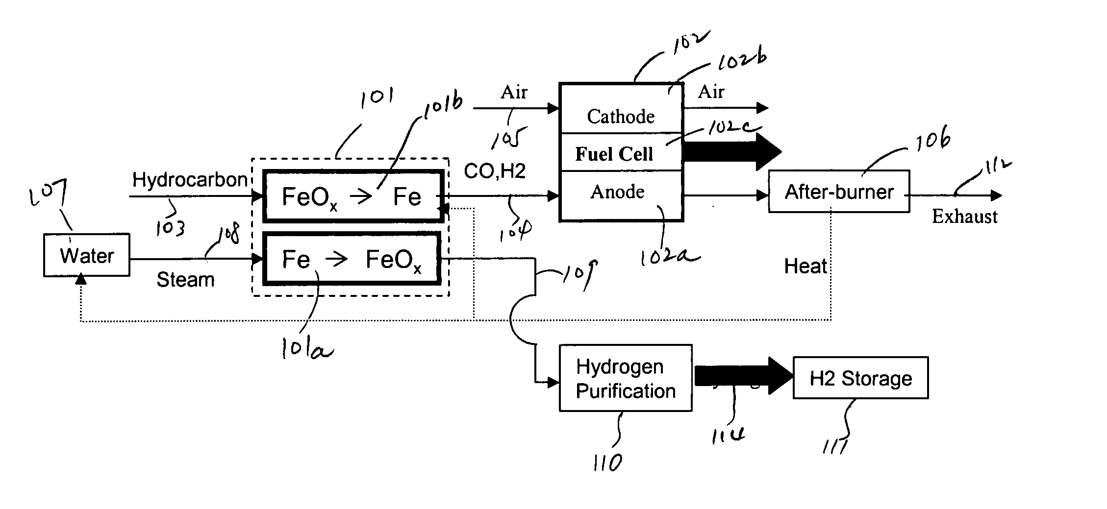
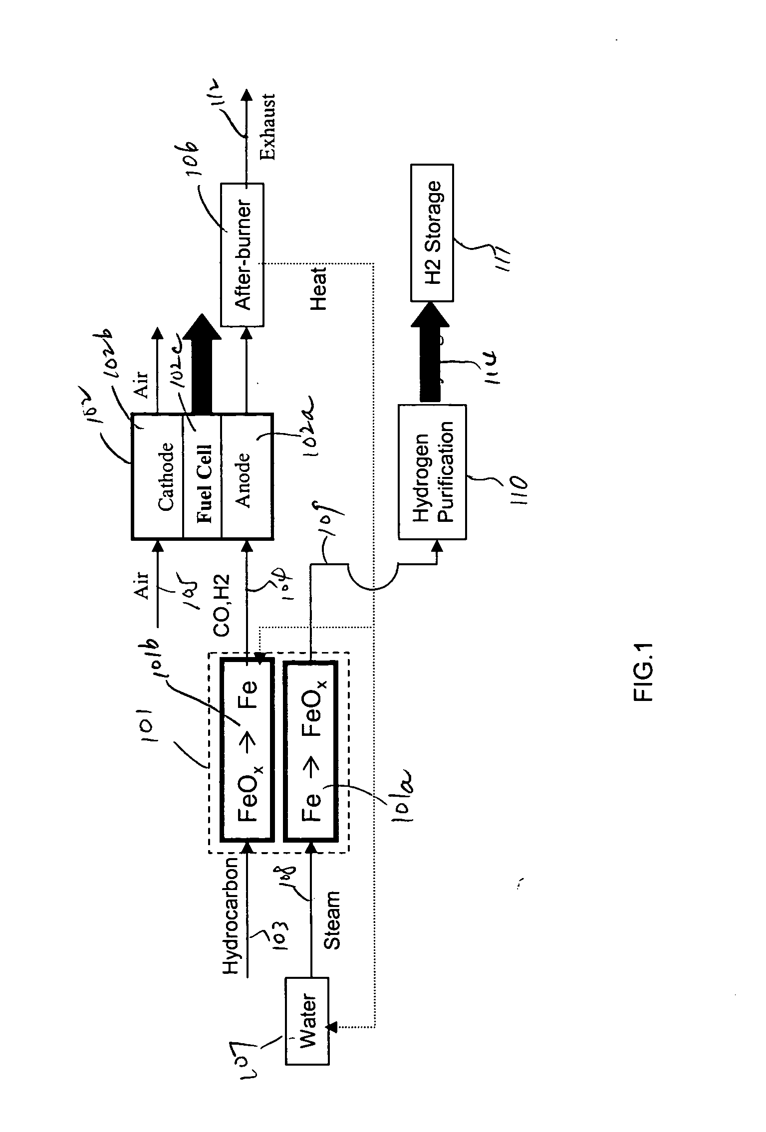
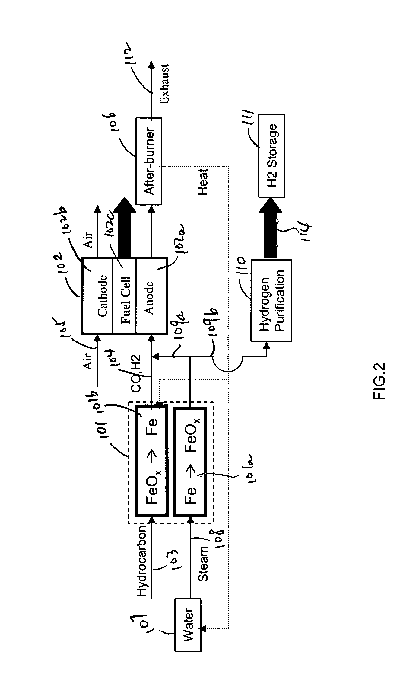
In this detailed description, “fuel cell” and “fuel cell unit” also refer to one or more fuel cell stacks. A fuel cell is often formed by multiple identical fuel cell stacks. One kind of such fuel cell, known as “solid oxide fuel cell” (SOFC), is a ceramic fuel cell having an oxygen conducting electrolyte. SOFCs, which typically operate at temperatures between 400 to 1000° C., are made in tubular, planar or monolithic forms. These fuel cells use a hydrocarbon fuel, which may be any carbonaceous fuels, including natural gas, propane, methane, all paraffins, methanol, ethanol, propanol, gasoline, and diesel.

Because iron can have many oxidation states, there are many different iron oxide compounds, ranging from oxidation state 0 (i.e., elemental iron) to 3 (i.e., ferric oxide or Fe2O3), and many intermediate oxides FeOx, where x<1, FeO and Fe3O4. The present invention uses these oxidation states of iron to store oxygen. To simplify this detailed description, unless specified ex...


PUM

PropertyMeasurementUnit
temperatureaaaaaaaaaa

Abstract

A method and a system for the co-production of electricity and hydrogen fuel are provided. The system may include a fuel conditioning unit, two or more iron / iron oxide beds and a high temperature electrochemical generator. In one embodiment, a reduction bed contains iron oxides. A hydrocarbon fuel, such as natural gas, is conditioned to carbon dioxide and hydrogen by the reduction bed. The conditioned fuel is then converted electrochemically to generate electricity in a fuel cell. Operating simultaneously is an oxidation bed that oxidizes elemental iron to iron oxides and produces hydrogen. The oxidation bed may previously have served as the reduction bed. The hydrogen thus produced is sufficiently pure to be used in a refueling application. The heat necessary for the endothermic reduction may be provided by the high temperature electrochemical generator. The two beds may operate concurrently or sequentially, and alternate their roles when their reactants are partially exhausted.

Description

BACKGROUND OF THE INVENTION 1. Field of the Invention The present invention relates to the energy conversion processes and fuel processing in fuel cells. In particular the present invention relates to systems and processes for on-site production of hydrogen and other fuels to operate fuel cells. 2. Discussion of the Related Art Concerns about greenhouse gas effects have generated great interest in developing energy technologies with low emissions. Fuel cells, owing to their much higher efficiencies, have the potential to reduce greenhouse gas emissions by one half or more. For this reason, fuel cells are believed suitable for stationary power generation and transportation applications. One of the hurdles that have hampered extensive use of fuel cells is the absence of a hydrogen fuel infrastructure. Indeed, hydrogen is by far the preferred fuel for most fuel cells, and particularly for the Polymer Electrolyte Membrane Fuel Cells (PEMFCs), the leading candidate for transportatio...

Claims


Application Information

Patent Timeline
Patent Type & Authority Applications(United States)
IPC IPC(8): C01B3/10C01B3/24
CPCC01B3/105C01B3/24C01B2203/0266Y02E60/50C01B2203/84H01M8/0618Y02E60/36C01B2203/066
Inventor PHAM, AI QUOC
Owner EVOGY
Why Eureka
Try Eureka