Tubular solid oxide fuel cells

a fuel cell and tubular technology, applied in the field of solid electrolyte electrochemical cells, can solve the problems of low power output, brittleness and difficult machine, and brittleness of ceramic plates, so as to achieve low electrical resistance, strong electrical contact, and low cost.

Inactive Publication Date: 2005-02-17
EVOGY
View PDF12 Cites 72 Cited by
  • Summary
  • Abstract
  • Description
  • Claims
  • Application Information

AI Technical Summary

Benefits of technology

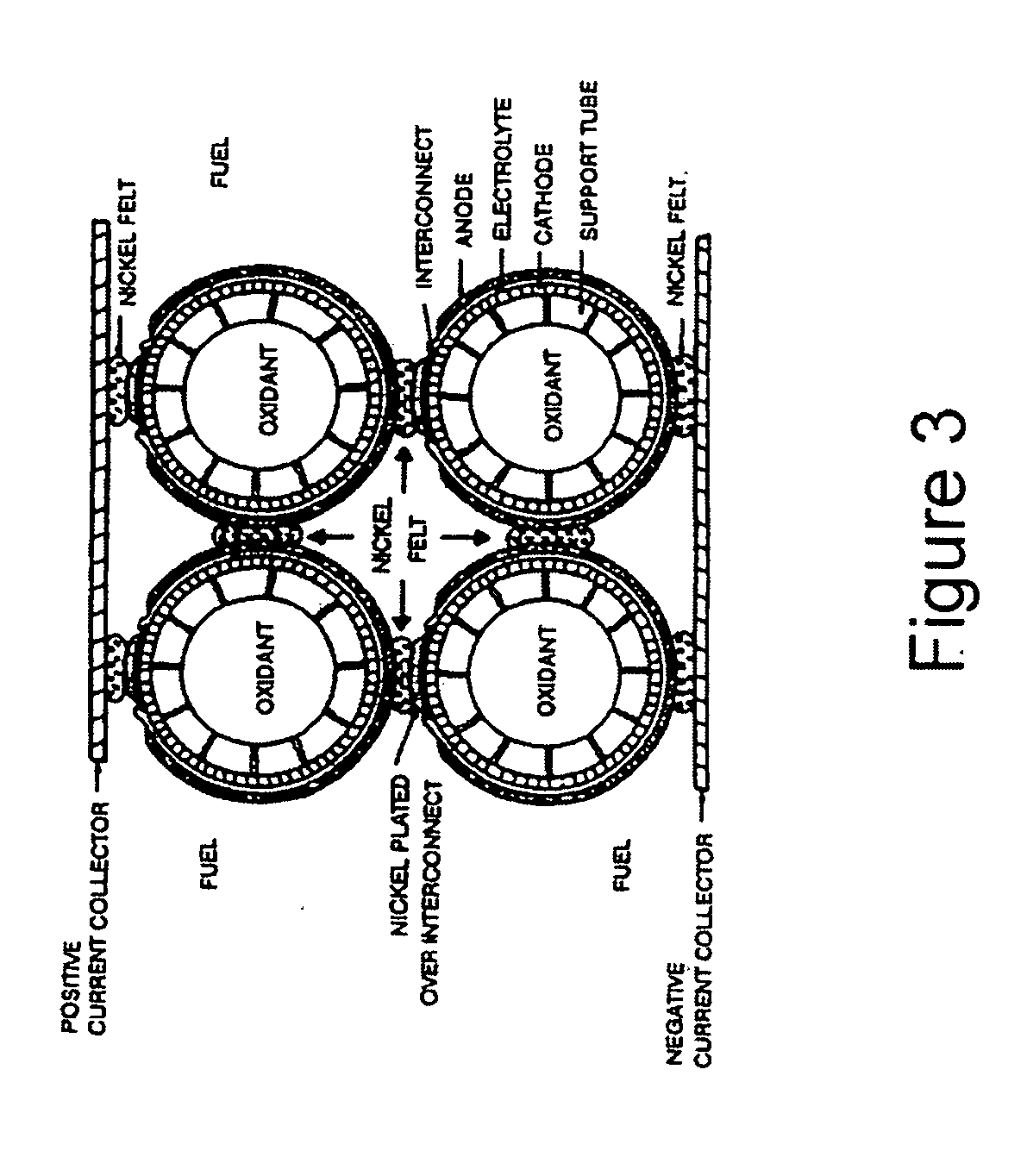
[0023] According to one embodiment of the present invention, an anode-supported tubular fuel cell stack is provided having interconnect components that are oxidation-resistant at high temperatures, flexible enough both to accommodate thermal expansion stress and to provide strong electrica

Problems solved by technology

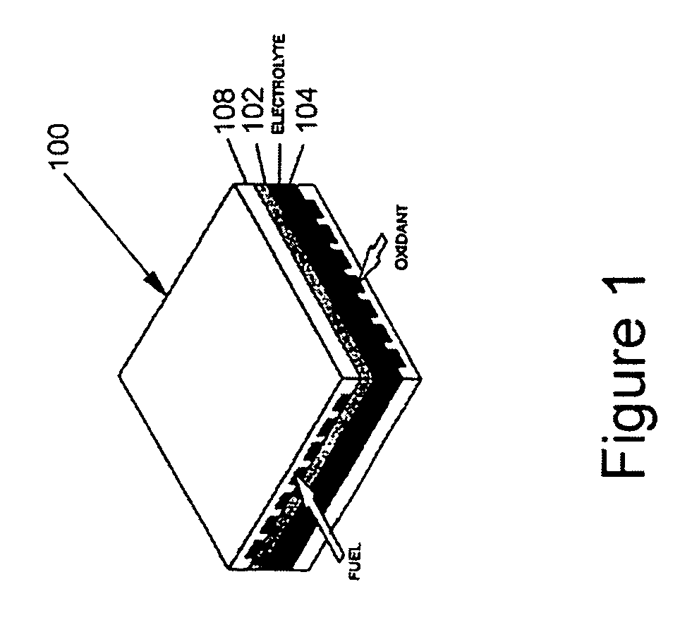
One disadvantage of an electrolyte-supported fuel cell is the low power output because of the large ohmic resistance of the thick electrolyte layer.
The cathode, which may be made from doped lanthanum manganite, is mechanically weaker, but more expensive, than the anode, which may be made of ceramic metallic composite of nickel and stabilized zirconia.
A ceramic plate is typically expensive, brittle and difficult to machine.
A metallic interconnect plate, however, loses conductivity because of metal oxidation at high temperature.
Metallic interconnect plates in planar fuel cells experience high mechanical stress induced by the mismatch between the low expansion ceramic and the high expansion alloys, and the oxidation and corrosion of the alloys in air and fuel environments.
The flat ceramic plates, which are typically thinner than 1 mm while having an aspect ratio greater than 100, tend to fracture easily.
In a planar fuel cell stack, the extensive sealing area and the absence of an effective seal are major technical issues.
Planar fuel cells require high temperature seals and must endure a higher mechanical stress resulting from the mismatched thermal expansion coefficients of the brittle ceramic fuel cells and the interconnect components.
The difference in thermal expansions between the ceramic fuel cell components and the metallic interconnects during thermal cycles also contributes to fracture and seal leaks.
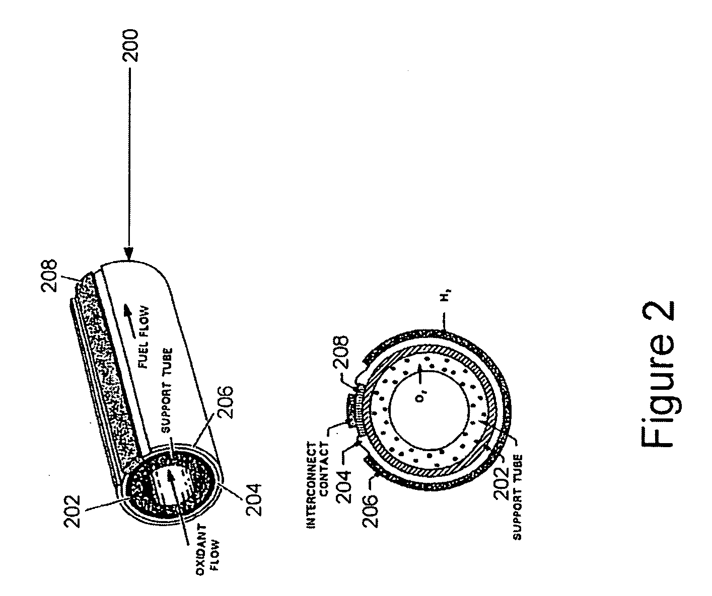
A cathode-supported tubular fuel cell has a high fabrication cost because of the expensive cathode material and the complex fabrication technique (e.g., chemical vapor deposition) necessary to provide

Method used


Image

  • Tubular solid oxide fuel cells
  • Tubular solid oxide fuel cells
  • Tubular solid oxide fuel cells

Examples


Embodiment Construction

[0043] The present invention provides a tubular anode-supported fuel cell that has a higher power density and enhanced mechanical strength over a prior art planar fuel cell. The present invention further provides a flexible, lightweight, and economical electrical interconnect components for interconnecting anode-supported fuel cell.

[0044]FIG. 4 shows an anode-supported SOFC 400, in accordance with one embodiment of the present invention. As shown in FIG. 4, SOFC 400 includes porous support tube 402, which may be between 0.1 to 4 mm thick (more preferably between 0.5 to 2 mm thick) and between ¼ inch to 1 inch in diameter (preferably between ¼ to {fraction (3 / 4)} inch). A smaller diameter shortens the current path and thus reduces ohmic resistance loss. Support tube 402 may be made from a wide variety of materials, including alumina, doped-zirconia, doped lanthanum chromite. To minimize the ohmic loss due to electrical conduction along the circumference of the tube, the tube materia...


PUM


Abstract

An anode-supported tubular fuel cell stack includes interconnect structures that are oxidation resistant at high temperature, flexible to accommodate thermal expansion stress and to provide strong electrical contact, have low electrical resistance, and are inexpensive and light weight. The interconnect structures may be formed out of metal sheet, which provide improved heat homogeneity throughout the fuel cell stack because of the high thermal conductivity of the metal. The interconnect structures are further shaped to provide resilience or spring-like features to allow movement between the tubular cells. Thus good electrical contact, thermal stress release, and shock absorption are simultaneously achieved.

Description

CROSS-REFERENCE TO RELATED APPLICATIONS [0001] This application claims priority of U.S. Provisional Patent Application No. 60 / 494,379, entiled “Tubular Solid Oxide Fuel Cells”, filed on Aug. 6, 2003.BACKGROUND OF THE INVENTION [0002] 1. Field of the Invention [0003] The present invention relates to solid electrolyte electrochemical cells; more particularly, the present invention relates to anode-supported tubular electrochemical cells and methods for electrically connecting such electrochemical cells in various configurations to provide various voltages and currents required by many applications. [0004] 2. Discussion of the Related Art [0005] Fuel cells are electrochemical devices that convert chemical fuels directly into electricity without combustion. A fuel cell typically includes an electrolyte membrane sandwiched between two electrodes: a cathode in contact with a source of air (“air electrode”) and an anode in contact with the chemical fuels (“fuel electrode”). Among the vario...

Claims


Application Information

Patent Timeline
IPC IPC(8): H01M8/10H01M8/12H01M50/528
CPCH01M4/9025Y02E60/50H01M8/1226H01M4/9033
Inventor PHAM, AI QUOC
Owner EVOGY
Why Eureka
Try Eureka