Microchannel heat exchangers and methods of manufacturing the same

a heat exchanger and microchannel technology, applied in the field of heat exchanger systems, can solve the problems of limited availability of compatible heat sink coolants, machining or etching capabilities, and limiting the size, number and configuration of channels that can be fabricated on the surface of the structure, so as to optimize the thermal and hydrodynamic performance of the heat exchanger, and maximize the effect of thermal performan

Inactive Publication Date: 2005-02-24
ADVANCED CERAMICS
View PDF14 Cites 38 Cited by
  • Summary
  • Abstract
  • Description
  • Claims
  • Application Information

AI Technical Summary

Benefits of technology

An analytical model can be utilized to characterize and optimize the thermal and hydrodynamic performance of a heat exchanger. The model allows an optimum number of layers to be identified to maximize thermal performance for given channel dimension and pumping power.

Problems solved by technology

While MCMs offer considerable reduction in both the microelectric packaging volume and interconnection signal delay, the integration results in higher heat fluxes.
The methods of connecting the signals and power from the MCM to the next level package (e.g., printed wiring board or 3-D MCM stack) presents heat removal challenges.
Further confounding thermal management of aircraft electronics is a limited availability of compatible heat sink coolants at suitable temperatures.
Thus, the machining or etching capabilities will limit the size, number and configuration of the channels that can be fabricated on the surface of the structure.
The need for secondary bonding processes to fabricate a heat sink also presents challenges.
While this concept is efficient, it is a very complicated structure to fabricate and therefore expensive.

Method used


Image

  • Microchannel heat exchangers and methods of manufacturing the same
  • Microchannel heat exchangers and methods of manufacturing the same
  • Microchannel heat exchangers and methods of manufacturing the same

Examples


example 1

This example illustrates an analytical model that can be applied to characterize and optimize a heat exchanger device. A closed-form analytical solution for the overall thermal resistance of single and multi-layered channels is evaluated. Optimization work is presented to obtain the optimum number of layers to maximize thermal performance for a given pumping power. The analytical solution allows for an efficient parametric study to determine the optimum design parameters. The constants and variables used in the model are defined in Table I.

TABLE IDESCRIPTIONSYMBOLachannel height, (m)Aarea, (m2)bchannel width, (m)cpspecific heat of water, (J / kg · C.)Dhhydraulic diameter, (m)ffriction factorhbase thickness, (m){overscore (h)}heat transfer coefficient, (W / m2 · C.)Hsample thickness, (m)kthermal conductivity (W / m · C.)Lsample length, (m){dot over (m)}mass flow rate, (kg / s)nnumber of channelsNuNusselt numberΔppressure, (Pa)Ppumping power, (W)Pwwetted perimeter, (m)PrPrandtl numberqheat...

example 2

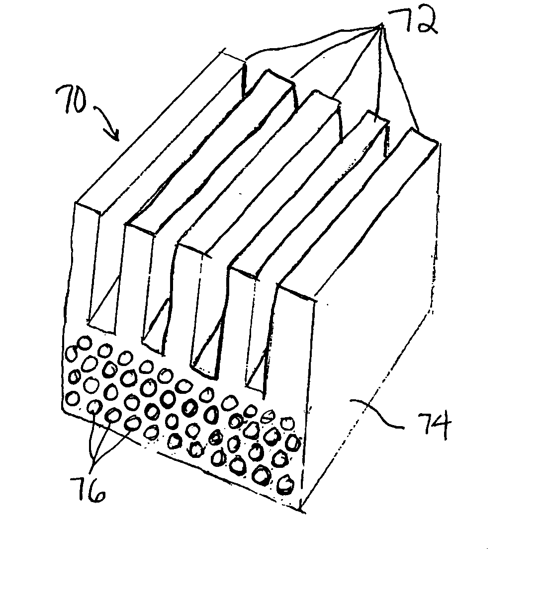
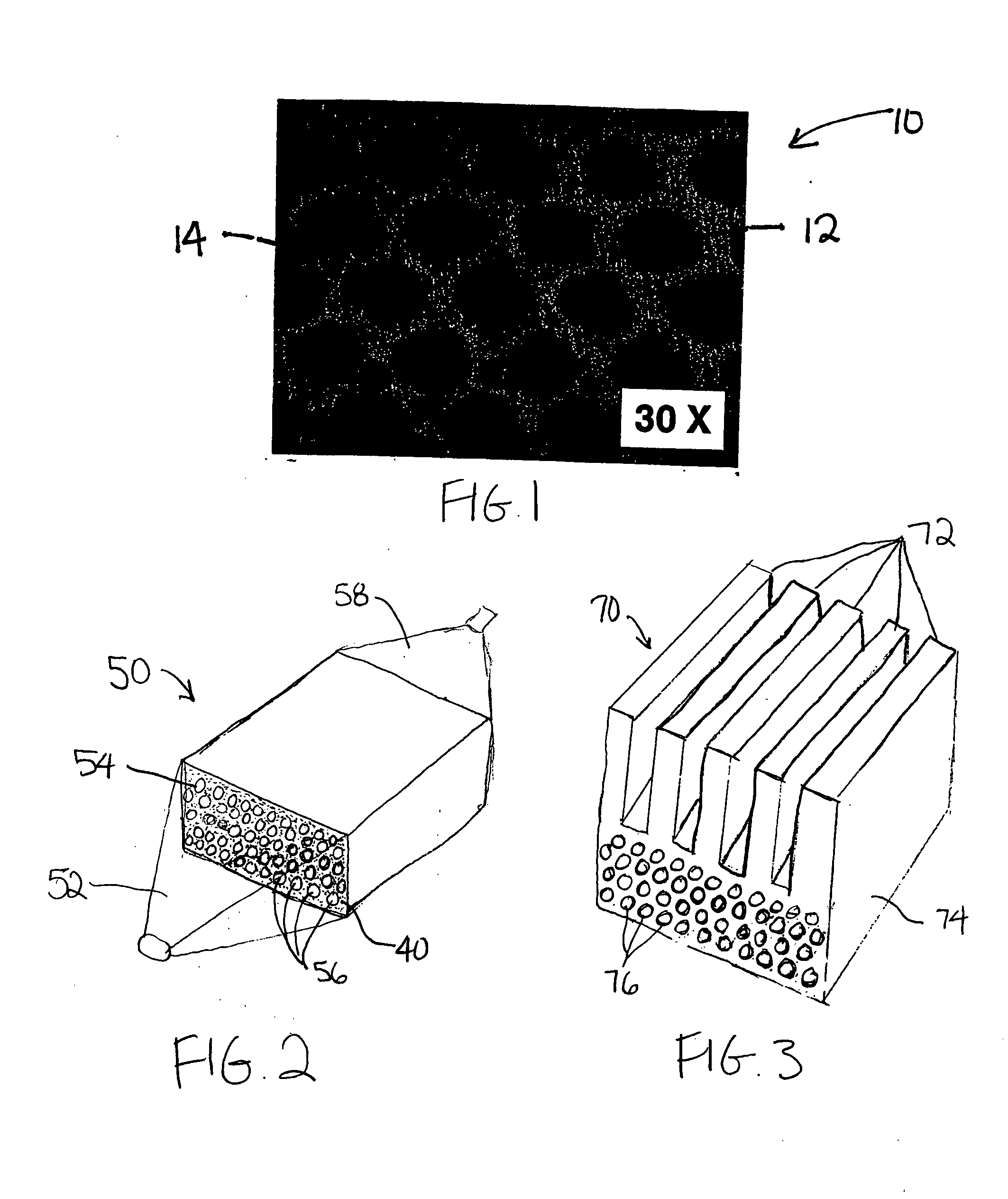
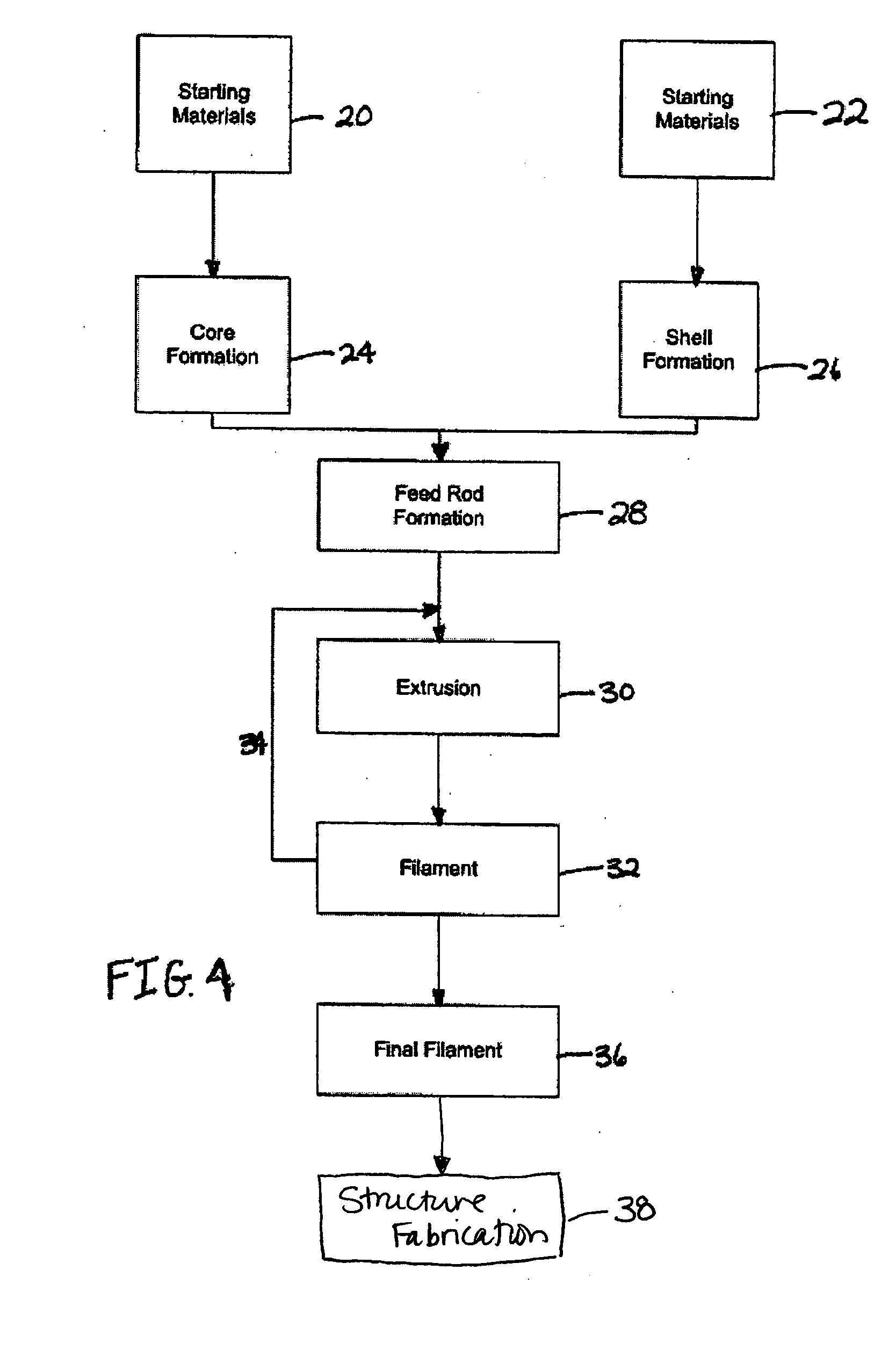
A heat exchanger having SiC channels was fabricated. The overall thermal resistance of the heat exchanger decreased and the pressure drop increased with increased mass flow rate of the coolant, as illustrated in FIG. 11. For fixed heat sink dimensions, channel diameter and porosity varied, as illustrated in FIGS. 12 and 13. An optimum number of rows of channels was determined for the heat exchanger, as illustrated in FIG. 14.


PUM

PropertyMeasurementUnit
inner diametersaaaaaaaaaa
temperatureaaaaaaaaaa

Abstract

A heat exchanger device includes an extruded body that includes one or more layers of channels for coolant flow therethrough, the channels generally having inner diameters of between about 50 microns to about 2000 microns. The device is formed of a material having a high thermal conductivity to facilitate transfer of heat from the heating components present in the subject cooling application to the coolant passing through the heat exchanger and to be compatible with materials of the heating components. The device material is selected from the group consisting of ceramic oxides, ceramic carbides, ceramic nitrides, ceramic borides, ceramic suicides, metals, and intermetallics, and combinations thereof. The heat exchanger device is formed from an extruded filament that is arranged to give the desired channel configuration. The filament includes a central, removable material and an outer material that forms the channel walls upon removal of the central material.

Description

BACKGROUND OF THE INVENTION The present invention relates to heat exchanger systems for use generally with electronic applications. More particularly, the present invention relates to heat exchanger bodies having oriented micro-scale channels and methods of fabricating such bodies. Rapid advances in large-scale integrated electronics packaging, lightweight composite structures, and high conductivity materials are enabling the development of new manufacturing and integration technology called multifunctional structures (“MFS”). The main MFS concept is to embed electronics assemblies (e.g., multi-chip modules, or “MCM”), integral thermal management, miniature sensors, and actuators into load carrying structures along with associated embedded cabling for power and data transmission. This integration yields major weight, volume and cost savings. While MCMs offer considerable reduction in both the microelectric packaging volume and interconnection signal delay, the integration results ...

Claims


Application Information

Patent Timeline
Patent Type & Authority Applications(United States)
IPC IPC(8): F28DH01L21/48H01L23/373H05K5/06
CPCF28F7/02F28F2260/02H01L21/4871H01L23/3731H01L23/473Y10T29/49359H01L2924/0002F28F2255/16Y10T29/4935H01L2924/00B23P15/26
Inventor VAIDYANATHAN, K. RANJIORTEGA, ALFONSOPLATERO, MARLENESKANDAKUMARAN, PRATHIBBOWER, CHAD
Owner ADVANCED CERAMICS
Why Eureka
Try Eureka