[0011] According to this constitution, the present invention can supply the piezoelectric vibration reed with a signal output from, for example, other oscillator as the excitation signal to excite forcibly the piezoelectric vibration reed, without exciting the piezoelectric vibration reed for the mass measurement by the oscillation circuit. Accordingly, even when a CI value becomes larger or Q value is lowered due to the immersion of the piezoelectric vibration reed in liquid, the piezoelectric vibration reed can be excited stably, and reliable measurement of a very small mass can be performed.
[0013] According to the above-described constitution of the present invention, the phase detection unit calculates the
phase difference between the excitation signal outputted from the
voltage controlled oscillator and the output signal of the piezoelectric vibration reed which is forcibly excited by the excitation signal, and the control voltage output unit supplies the voltage corresponding to the phase difference to the
voltage controlled oscillator and allows the frequency of the excitation signal outputted from the
voltage controlled oscillator to coincide with the frequency of the output signal of the piezoelectric vibration reed. In other words, the voltage controlled oscillator, the phase detection unit and the control voltage output unit constitute a PLL (
phase locked loop) circuit. Accordingly, it is possible to allow the phase of the excitation signal outputted from the voltage controlled oscillator to coincide with the phase of the output signal of the piezoelectric vibration reed, and frequencies thereof can coincide with each other. The piezoelectric vibration reed does not constitute a self-excitation
resonance circuit, so that the piezoelectric vibration reed can be stably excited, even when the piezoelectric vibration reed is immersed in liquid, and the CI value becomes high. For this reason, the measurement using the piezoelectric vibration reed for the mass measurement can be reliably performed even in liquid. For the voltage controlled oscillator, a voltage controlled quartz oscillator (VCXO), a voltage controlled SAW oscillator (VCSO), and the like may be used. Moreover, the phase detection unit may consist of a phase
comparator, a
phase detector, and the like. Then, the control voltage output unit may consist of a
low pass filter, and the like.
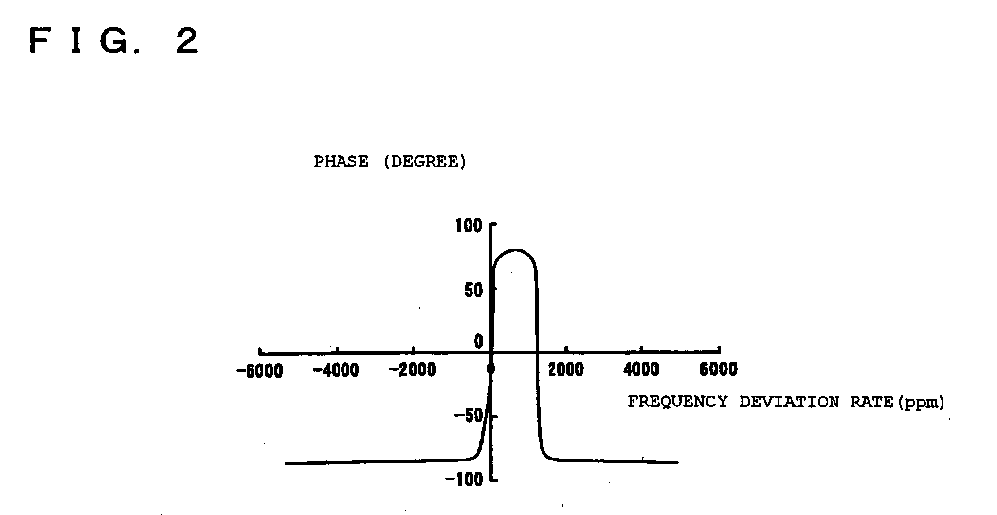
[0015] Between the voltage controlled oscillator and the phase detection unit, a phase shifter may be disposed, which delays or advances the phase of the excitation signal. When the piezoelectric vibration reed is immersed in liquid, if the phase in the
resonance frequency does not change sufficiently as described above, the phase of the excitation signal to be compared with that of the resonance frequency is adjusted to be delayed or advanced. Accordingly, the phase of the excitation signal to be supplied to the piezoelectric vibration reed can be coincided with the phase of the output signal of the piezoelectric vibration reed in the vicinity of the series resonance frequency of the piezoelectric vibration reed. Further, it is possible to allow the frequency the excitation signal outputted from the voltage controlled oscillator to coincide with the frequency of the output signal of the piezoelectric vibration reed. Accordingly, the detection of the vibration frequency of the piezoelectric vibration reed and the mass measurement in liquid become possible. Moreover, to detect more accurately the series resonance frequency of the piezoelectric vibrator, a difference between the series resonance frequency and a phase
zero frequency by the parallel
capacitance of the piezoelectric vibrator can be corrected through the phase shifter.
[0016] Moreover, in the present invention, a multiplier may be provided in an output side of the voltage controlled oscillator. Through this multiplier, the excitation signal may be supplied to the piezoelectric vibration reed and the phase detection unit. Accordingly, even when the resonance frequency of the piezoelectric vibration reed is a
high frequency, it is possible to use a voltage controlled oscillator for a
low frequency, convert a output signal (an excitation signal) from the voltage controlled oscillator into a
high frequency signal by the multiplier and supply the
high frequency signal to the piezoelectric vibration reed, thereby making the excitation circuit cheaply. Then, in case of converting the output signal of the voltage controlled oscillator into the high frequency signal by the multiplier, a divider may be advantageously disposed between the piezoelectric vibration reed and the phase detection unit, and between the multiplier and the phase detection unit. By converting the high frequency excitation signal and the output signal of the piezoelectric vibration reed into
low frequency signals through the divider, the phase detection unit or the control voltage output unit can be made with a circuit constitution for
low frequency, thereby the excitation circuit being made cheaply. Moreover, high frequency
processing units can be reduced, and affect of
noise and the like can be decreased.
[0017] The phase detection unit and the control voltage output unit can be made with digital circuits. As a result, an integrated circuitry of a circuit becomes easy, and the
miniaturization can be planned. In this case, a
charge pump may be provided between the phase detection unit and the control voltage output unit. By providing the
charge pump, the output signal of the phase detection unit can be converted into
high voltage, and then an output of the control voltage output unit becomes larger, which allows the voltage controlled oscillator to operate reliably. Moreover, the control voltage output unit may consist of a
digital signal processor. Accordingly, a high speed
processing can be realized and then the
noise in the measurement can be reduced.
[0018] Further, a plurality of the piezoelectric vibration reeds may be provided, and a switch unit for switching sequentially the piezoelectric vibration reeds to supply the excitation signal may be provided between the piezoelectric vibration reeds and the voltage controlled oscillator. Accordingly, multiple detection units of the measurement apparatus can be easily planned. Moreover, in the case of providing a plurality of the piezoelectric vibration reeds, the switch unit may be advantageously disposed between the piezoelectric vibration reed and the voltage controlled oscillator, and between the piezoelectric vibration reeds and the phase detection unit. Accordingly, when the excitation frequency of the piezoelectric vibration reed is a high frequency, it is possible to remove a trouble that the operation of the oscillation circuit becomes unstable. Then, the piezoelectric vibration reed may be the one for measurement in liquid which has the sensitive film only on one side surface thereof or the one for measurement in air which has the sensitive films on both side surfaces thereof.

