Heat source or heat sink unit with thermal ground coupling

a technology of heat sink and heat source, which is applied in the direction of geothermal energy generation, indirect heat exchangers, lighting and heating apparatus, etc., can solve the problems of high installation cost, high cost, and inability to use, and achieve the effect of preventing corrosion damage, promoting corrosion of drive-pipe segments, and avoiding corrosion damages

Inactive Publication Date: 2005-03-24
WATERKOTTE WARMEPUMPEN
View PDF16 Cites 57 Cited by
  • Summary
  • Abstract
  • Description
  • Claims
  • Application Information

AI Technical Summary

Benefits of technology

[0030] A further contribution to avoiding corrosion damages consists in using pipes for the piping of the remaining system and for its connection with a heating or cooling ...

Problems solved by technology

Such panel collectors require extensive earthworks, thus causing expensive installation; in addition, they can often not be used owing to local conditions.
It is also obvious that the establishment of such a system is very complicated and, thus, expensive.
In addition, such systems require official approval, so that additional cost and time expenditures are caused by the appropriate application for and processing of the approvals.
What is more and as practical observations have shown, the responsible authorities often treat such applications in a restrictive manner and with exaggerated care as regards the potential contamin...

Method used


Image

  • Heat source or heat sink unit with thermal ground coupling
  • Heat source or heat sink unit with thermal ground coupling
  • Heat source or heat sink unit with thermal ground coupling

Examples


Embodiment Construction

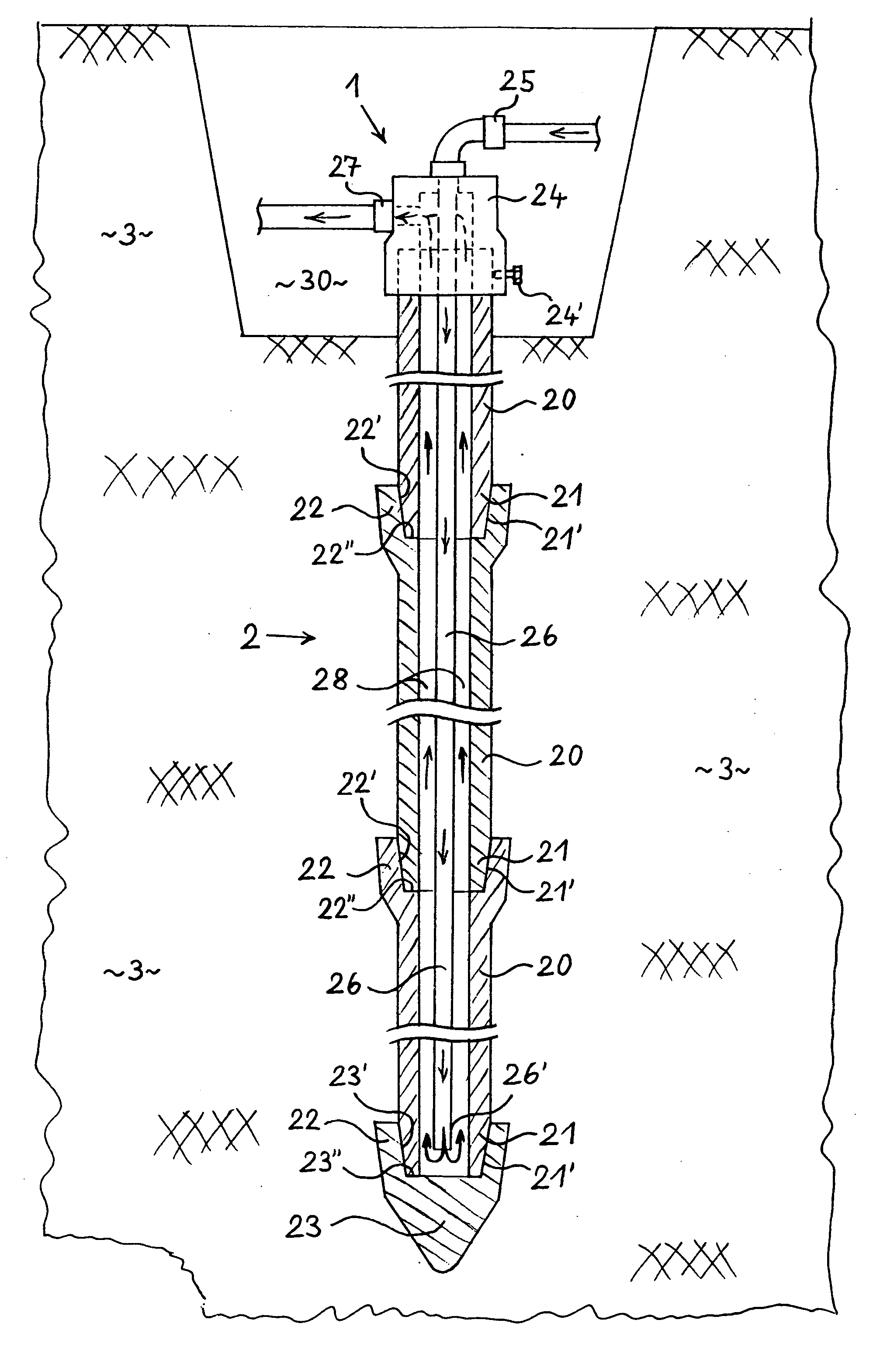
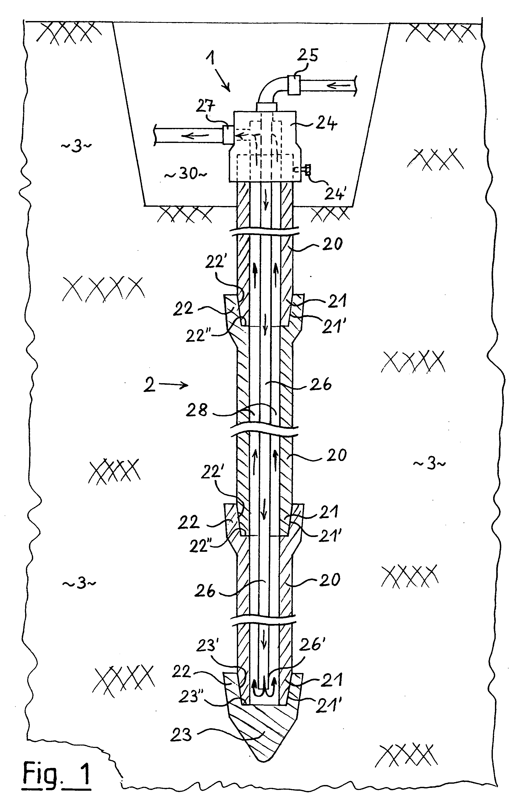
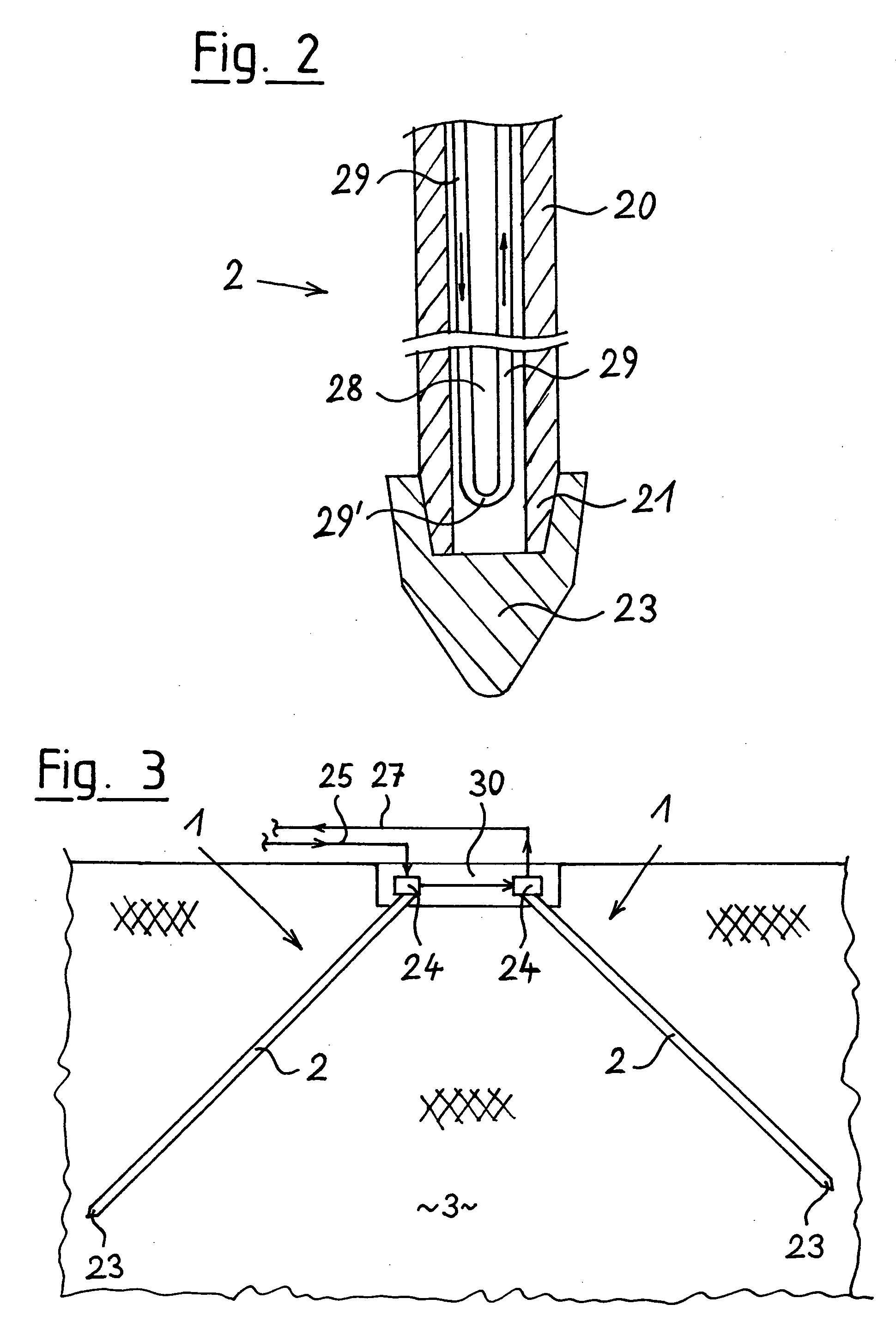
[0035] According to the executive example shown in FIG. 1, the ground probe 1 consists of a probe shaft 2 that is composed of several drive-pipe segments 20. To form the ground probe 1, the required number of drive-pipe segments 20 are initially driven successively into the ground 3 in a relatively small building pit 30 that has been prepared beforehand, for example by means of a hydraulic hammer mounted to an excavator arm or a carriage. At first, the drive-pipe segment 20 that is the bottommost in the drawing is provided with a probe tip 23 in order to ensure that said drive-pipe segments 20 can be driven into the ground 3 with as low a resistance as possible and as easily and quickly as possible. Herein, the probe tip 23 is tightly connected to the forward end 21 of the lower drive-pipe segment 20. As soon as the first drive-pipe segment 20 has been driven into the ground 3 almost completely, a second drive-pipe segment 20 is fitted; thereafter, the first and second drive-pipe se...


PUM


Abstract

The invention relates to a heat source or a heat sink unit with thermal ground coupling, comprising at least one ground probe arranged in the earth, whereby each earth probe is a probe tube made from several pile tube segments. An open dip tube or a U-shaped tube loop is arranged in the probe tube at the open lower end thereof. Said unit is characterized in that each pile tub segment is made from ductile cast iron, the pile tube segments re embodied such as to plug into each other at the ends thereof and each pile tube segment comprises, at the one end thereof, a conical outer circumference and, at the other end thereof, a sleeve embodied with a shoulder stop having a matching conical internal circumference, whereby the diameter thereof and the cone angle are such that on driving in the pile tube segments a positive and sealed connection between the pile tube segments is generated.

Description

BACKGROUND OF THE INVENTION [0001] The present invention relates to a heat source or heat sink system with thermal ground coupling for near-surface recovery of thermal energy from the ground or for near-surface discharge of thermal energy into the ground, wherein the system comprises at least one ground probe arranged in the ground, wherein thermal energy can either be withdrawn from or discharged into the ground by means of a heat transfer fluid supplied through the ground probe, wherein each ground probe comprises a metallic probe shaft that is tight against the surrounding ground and consists of several drive-pipe segments driven into the ground, and wherein either an immersion pipe that is open at its lower end or a U-shaped pipe loop is arranged in the probe shaft for supplying or removing the heat transfer fluid. [0002] Systems for the aforementioned types of intended use are known from practice in various executive forms. In essence, these known solutions can be grouped in th...

Claims


Application Information

Patent Timeline
IPC IPC(8): F24J3/08F28D1/00
CPCF24J3/083Y02E10/125F24J3/084F24T10/17F24T10/15Y02E10/10
Inventor GUYNN, KEVIN W.WATERKOTTE, KLEMENS
Owner WATERKOTTE WARMEPUMPEN
Why Eureka
Try Eureka