System and process for reducing impurities

a technology of impurity gettering and filtering device, which is applied in the direction of secondary cell servicing/maintenance, separation process, instruments, etc., can solve the problems of clogging or otherwise significantly inhibiting gas flow through a downstream filter, problems within the electrolytic cell, and entrained particulates. clogging or other significant inability to achieve the effect of reducing the level of water

Inactive Publication Date: 2005-03-31
FLUORINE ON CALL
View PDF13 Cites 9 Cited by
  • Summary
  • Abstract
  • Description
  • Claims
  • Application Information

AI Technical Summary

Benefits of technology

[0009] An impurity gettering device can be installed between a source and a reactor to reduce an impurity from a fluid before it reaches the reactor. More particularly, the impurity gettering device can getter an inorganic, polar, hydrogen-containing impurity (e.g., water, ammonia, etc.) from a halogen-containing fluid (e.g., a fluorine-containing liquid or gas) by forming ligands to a metal-containing compound to form a complex. In one example, a fluid source may include hydrogen fluoride and some water. The hydrogen fluoride and water c

Problems solved by technology

This level of water can cause problems within an electrolytic cell.
The oxygen from water can cause problems with the operation of the cell.
The entrained particulates may clog or otherwise significantly inhibit gas flow through a downstream filter.
This compound has low electrical conductivity and can cause increased voltage requirements at the anode-electrolyte interface.
Further, the graphite fluoride (CFx)n, is unstable and reacts with fluorine to produce an undesirable gaseous byproduct, carbon tetrafluoride, CF4, thereby exposing additional elemental carbon of the carbon anode.
Regardless of the mechanism, consumption of the carbon anode can significantly reduce the operating life of the electrolytic cell.
Many of these water removal systems are not well suited when a fluorine-containing compound is involved.
An undesired reaction be

Method used


Image

  • System and process for reducing impurities
  • System and process for reducing impurities
  • System and process for reducing impurities

Examples


Embodiment Construction

[0024] Reference is now made in detail to the exemplary embodiments of the invention, examples of which are illustrated in the accompanying drawings. Wherever possible, the same reference numbers will be used throughout the drawings to refer to the same or like parts (elements).

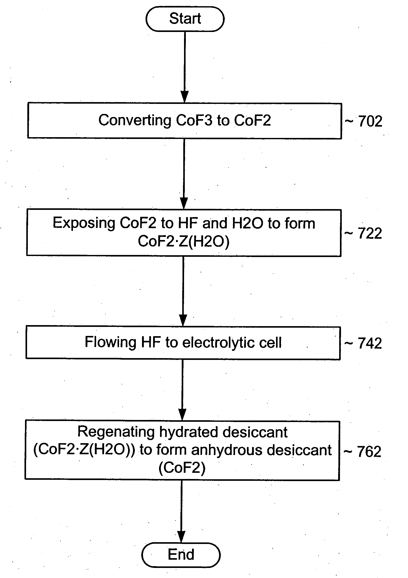
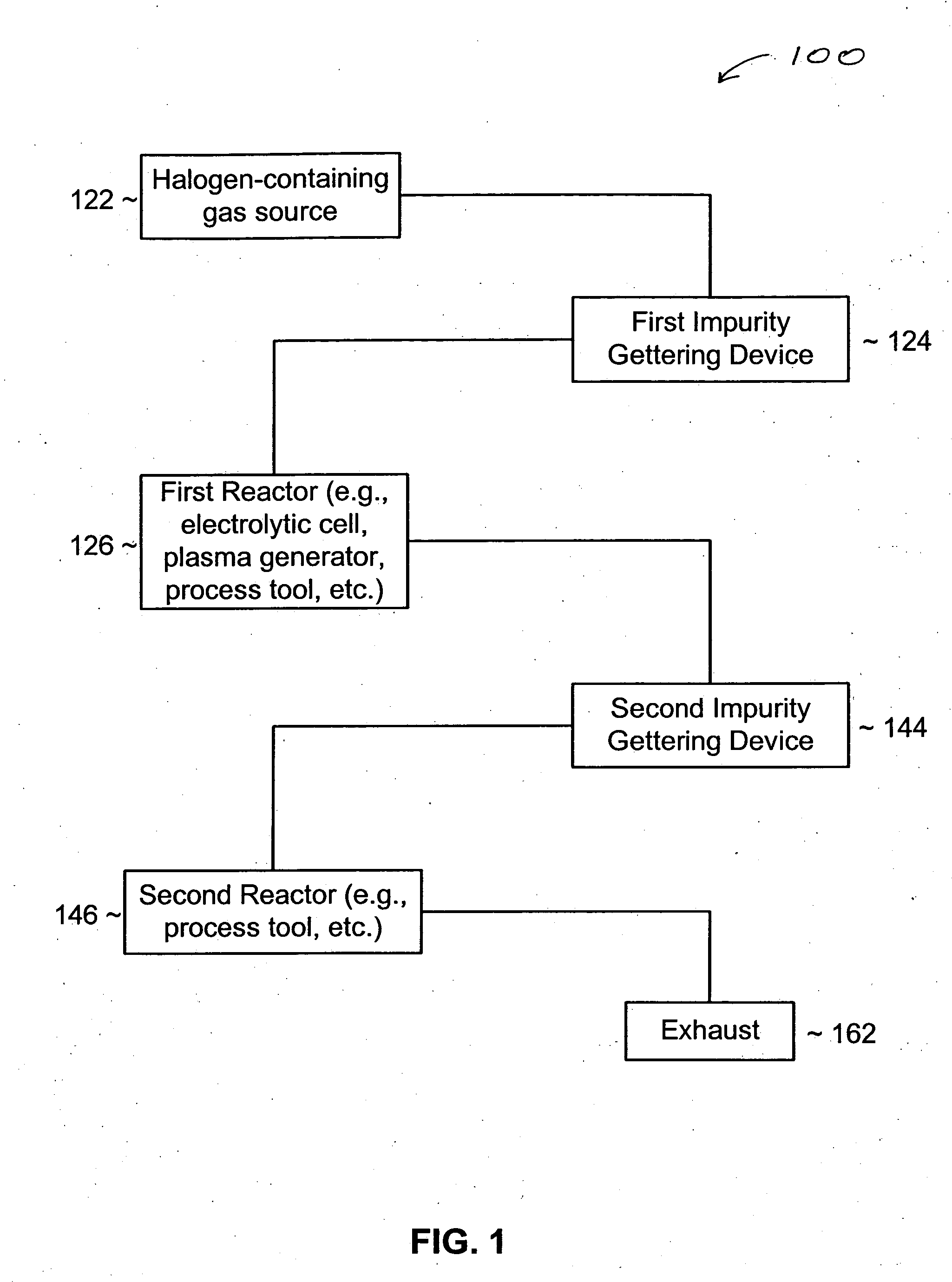
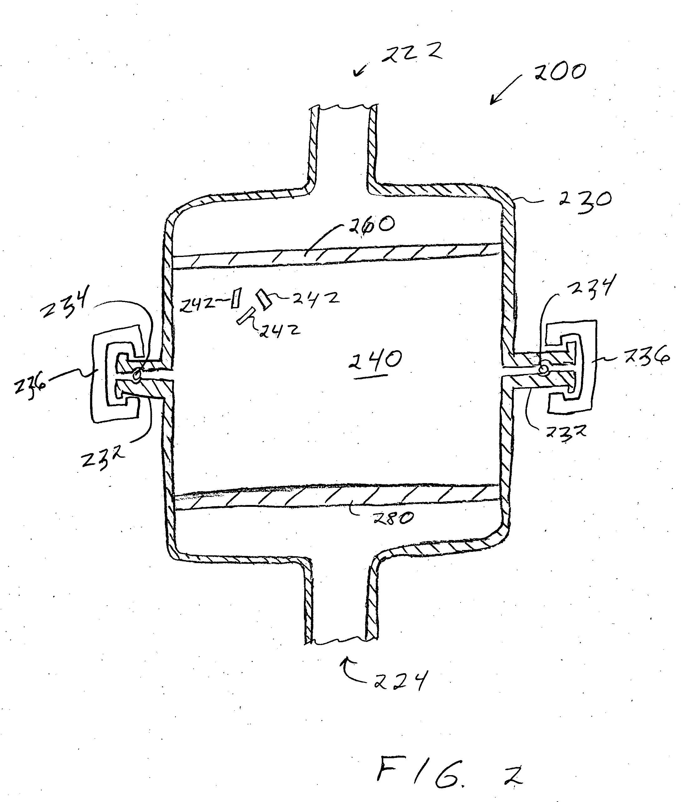
[0025] An impurity gettering device can be installed between a source and a reactor to reduce an impurity from a fluid before it reaches the reactor. More particularly, the impurity gettering device can getter an inorganic, polar, hydrogen-containing impurity (e.g., water (H2O), ammonia (NH3), etc.) from a halogen-containing fluid (e.g., a fluorine-containing liquid or gas) by forming ligands to a metal-containing compound to form a complex. In one example, a fluid source may include HF and some H2O. The HF and H2O can flow through the impurity gettering device that includes cobalt difluoride (CoF2). The CoF2 can getter the H2O and form a CoF2 hydrate. After removing or at least reducing the level of H2O in ...


PUM

PropertyMeasurementUnit
Fractionaaaaaaaaaa
Percent by massaaaaaaaaaa
Particle sizeaaaaaaaaaa

Abstract

An impurity gettering device can be installed between a source and a reactor to reduce an impurity from a fluid before it reaches the reactor. More particularly, the impurity gettering device can getter an inorganic, polar, hydrogen-containing impurity (e.g., H2O, NH3, etc.) from a halogen-containing fluid (e.g., a fluorine-containing liquid or gas) by forming ligands to a metal-containing compound to form a complex. In one example, a fluid source may include HF and H2O, which can flow through the impurity getting device that includes COF2. The COF2 can getter the H2O and form CoF2.ZH2O, where Z is an integer. The fluid may become anhydrous HF that can be processed by a reactor, such as an electrolytic cell. By removing H2O before the fluid reaches the electrolytic cell, adverse effects of H2O, such as consumption of a carbon anode, particle generation, etc. can be reduced.

Description

RELATED APPLICATIONS [0001] This application is related to U.S. patent application Ser. No. 10 / 038,745 entitled “Method And System For On-Site Generation And Distribution Of A Process Gas” by Jackson filed of Jan. 2, 2002; Ser. No. 10 / 193,864 entitled “System and Method for On-Site Generation and Distribution of Fluorine for Fabrication Processes” by Siegele et al. filed on Jul. 12 2002; and Ser. No. 10 / 283,433 entitled “Generation and Distribution Of Molecular Fluorine Within a Fabrication Facility” by Siegele et al. filed on Oct. 30, 2002, all of which are assigned to the current assignee hereof and are incorporated herein by reference.FIELD OF THE INVENTION [0002] The present invention generally relates to impurity gettering devices, and more particularly, to impurity gettering devices and processes of using them to remove impurities from halogen-containing fluids. DESCRIPTION OF THE RELATED ART [0003] The use of diatomic fluorine within semiconductor processing equipment is now ...

Claims


Application Information

Patent Timeline
IPC IPC(8): C01B9/08C01G51/08H01M10/05
CPCC01B9/08H01M10/05C01G51/08Y02E60/10
Inventor HAGE, DANIEL B.JACKSON, ROBERT
Owner FLUORINE ON CALL
Why Eureka
Try Eureka