

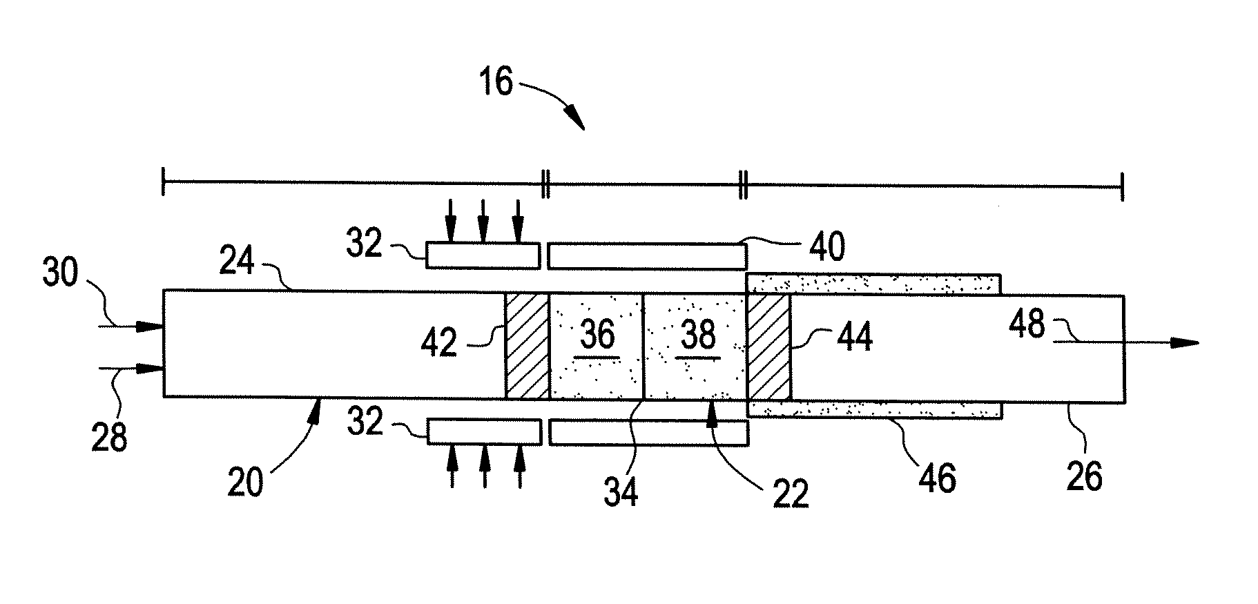
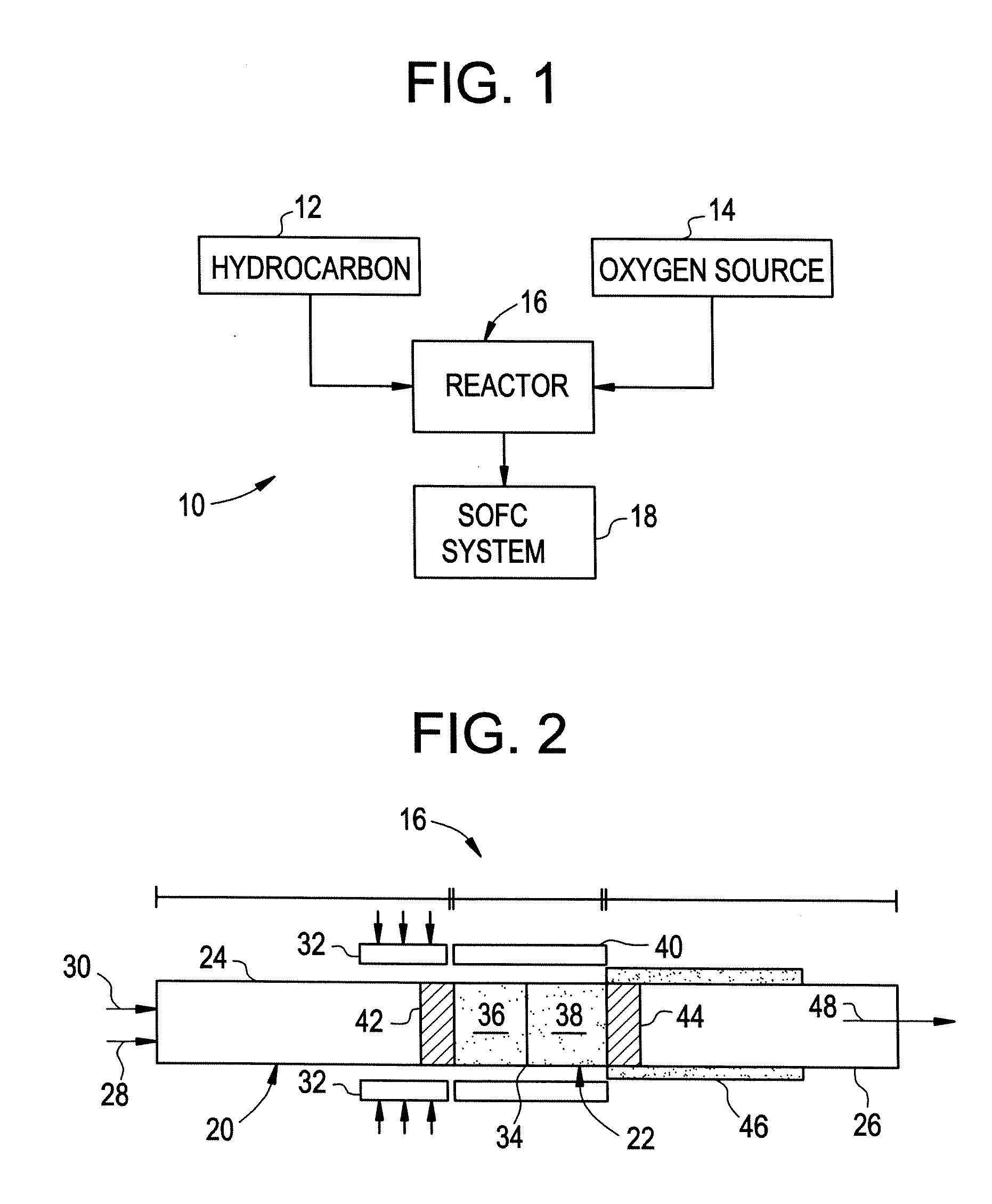
Thermally Managed Catalytic Partial Oxidation Of Hydrocarbon Fuels To Form Syngas For Use In Fuel Cells
a technology of hydrocarbon fuels and catalysts, which is applied in the direction of gas-gas reaction processes, chemical/physical/physicochemical processes, chemical apparatuses and processes, etc., can solve the problems of space and weight issues, slow required heat transfer processes, and design barriers in each of the three hydrocarbon conversion processes, so as to improve the throughput, yield and runtime of the process, and reduce the deposition of carbon and residual hydrocarbons
- Summary
- Abstract
- Description
- Claims
- Application Information
AI Technical Summary
Benefits of technology
Problems solved by technology
Method used
Image


Examples
example 1
Catalyst Preparation
[0044] The catalyst is prepared by impregnating the catalysts onto the surface of the open channel support structure. Rhodium and nickel configured in series on alpha alumina support is the catalyst system used. A soluble salt of the hydrated form of rhodium chloride is dissolved in demineralized water to make an aqueous solution with a concentration of rhodium of 10% by weight. The alumina support is prepared by baking in air at 500° C. for 2 hours. Using a microliter syringe, rhodium solution is then added dropwise to the alumina monolith support until the point of incipient wetness is reached. The catalyst is then dried in air at room temperature for 2 hours. The dried catalyst is then re-wetted (drop-wise) with rhodium chloride solution and re-dried. The process is repeated a few times depending on the extent of loading of the metal needed. Typically, five to six deposits of the 10% rhodium solution on a 100 mg alpha alumina support provide about 30 mg of r...
PUM
| Property | Measurement | Unit |
|---|---|---|
| temperature | aaaaa | aaaaa |
| temperature | aaaaa | aaaaa |
| temperature | aaaaa | aaaaa |
Abstract
Description
Claims
Application Information