
Thermal imaging system and method

a technology of thermal imaging and thermal resistivity, which is applied in the field of thermal imaging system and, can solve the problems of difficult measurement of change in resistivity, unsuitable for long distance measuring and imaging, and sensitive tes to heat exchange with its environment, etc., and achieves high thermal resistivity, large fill factor, and high sampling time of each pixel.

Inactive Publication Date: 2005-05-05
NAMAL TECH LTD
View PDF11 Cites 16 Cited by
  • Summary
  • Abstract
  • Description
  • Claims
  • Application Information

AI Technical Summary

Benefits of technology

[0014] The reduction to practice of the new concept (see below) proves that we can utilize a thermal link with high thermal resistivity, so that the IR radiation induces a temperature increase, which is compatible with the state of the art systems. The virtual absence of electrical noise, the lack of Joulean heating, the relatively large Fill Factor and, most importantly, the higher sampling time of each pixel guarantee improved performance of the detector and / or detectors array.

Problems solved by technology

Thermal detectors are implemented using a number of technologies, some of which (e.g., thermocouples) require direct contact with the measured object, and are therefore unsuitable for long distance measuring and imaging.
However, it should be noted that a TES is very sensitive to the heat it exchanges with its environment.
However, since the changes in temperature are quite small, the change in resistivity is difficult to measure.
This problem is particularly significant in un-cooled systems.
As mentioned above, the major drawback of un-cooled TES systems is their relatively high level of noise, which limits their performance.
First, the fact that the detector is at high temperature (=room temperature) leads to relatively large fluctuations in its black body radiation.
Second, the sampling time in bolometric detectors is quite small due to Joulean heat that develops during the reading process.
Third, a chopper is introduced in pyroelectric detectors, which means that about half of the IR radiation is lost.
Fourth, the current in pyroelectric detectors is a transient one, and thus the sampling time is limited by the electrical RC time constant.

Method used


Image

  • Thermal imaging system and method
  • Thermal imaging system and method
  • Thermal imaging system and method

Examples


embodiment 1

[0044] Embodiment 1 utilizes the crossed-polarizers configuration for a single detector, which is made of a paraelectric material as the EO ingredient. There are several paraelectric EO materials, such as LiTaO3, KTaO3, KTa1-yNbyO3 (known as KTN), K1-xLixTa1-yNbyO3 (KLTN), K1-xNaxTa1-yNbyO3 (KNTN), this list being by no means complete.

[0045] Paraelectric materials are defined by the absence of spontaneous electrical polarization. Since the EO effect relates to the electrical polarization, it therefore follows that any changes in the index of refraction induced by the EO effect will be a function of the product of the applied electric field and the material's dielectric constant. In the mathematical analysis below we limit ourselves to the case where the paraelectric material is also centro-symmetric, in which case the EO effect is quadratic with respect to the applied field. It should be noted, however, that similar equations can be developed also for the linear EO, as indeed for a...

embodiment 2

[0058] Embodiment 2 is in principle similar to Embodiment 1, with the addition of an extra dummy, which is placed in parallel to the detector (a “parallel dummy”). The role of the parallel dummy is to extract a reference readout signal, which will be subsequently used to null any contribution that is not associated with the IR radiation induced temperature increase. In a preferred embodiment, the parallel dummy is identical to the detector in all parameters, with the exception of the IR absorbing layer. The parallel dummy is placed near the detector, so that both are supported by the same temperature controller.

[0059]FIG. 5 shows schematically the mode of operation of embodiment 2. A laser beam 51 is split to two equi-intensity beams 52 and 53 using a beam splitter (not shown). Alternatively, we can use two different laser beams, of preferably equal intensity and identical state of polarization. However, the usage of two different lasers is likely to enhance the noise, since their ...

embodiment 3

[0063] Embodiment 3 is another example for a single detector, this time utilizing the MZI configuration. A schematic description of this configuration is given in FIG. 6. A laser beam 61 is split to two equi-intensity beams, a reading beam 62 that passes through a detector 64 and a reference beam 63 that passes through a parallel dummy 65. A phase matching device 66 is added to one of the paths. In the case shown in FIG. 6, device 66 is added in the path of reference beam 63 without loss of generality. As explained in Embodiment 1 above, device 66 may be passive (i.e., of fixed properties), or active (i.e., made of an EO material whose degree of birefringence is controlled by an electric field). The beams are then brought together to interfere at a power meter 67. In the absence of IR radiation, the phase of the two beams should be identical (since the optical length they pass is identical), and therefore a constructive interference should be formed. The phase matching device is the...


PUM


Abstract

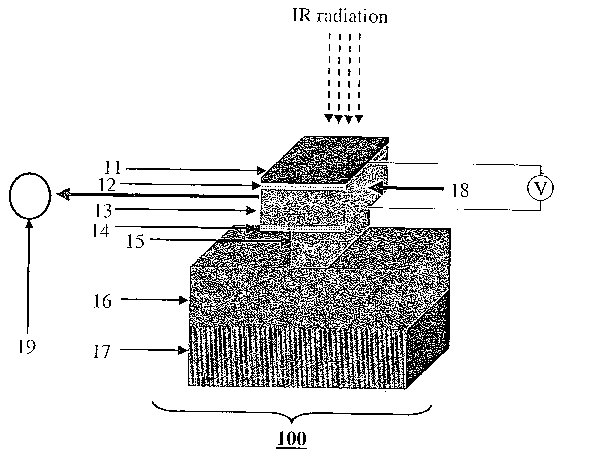
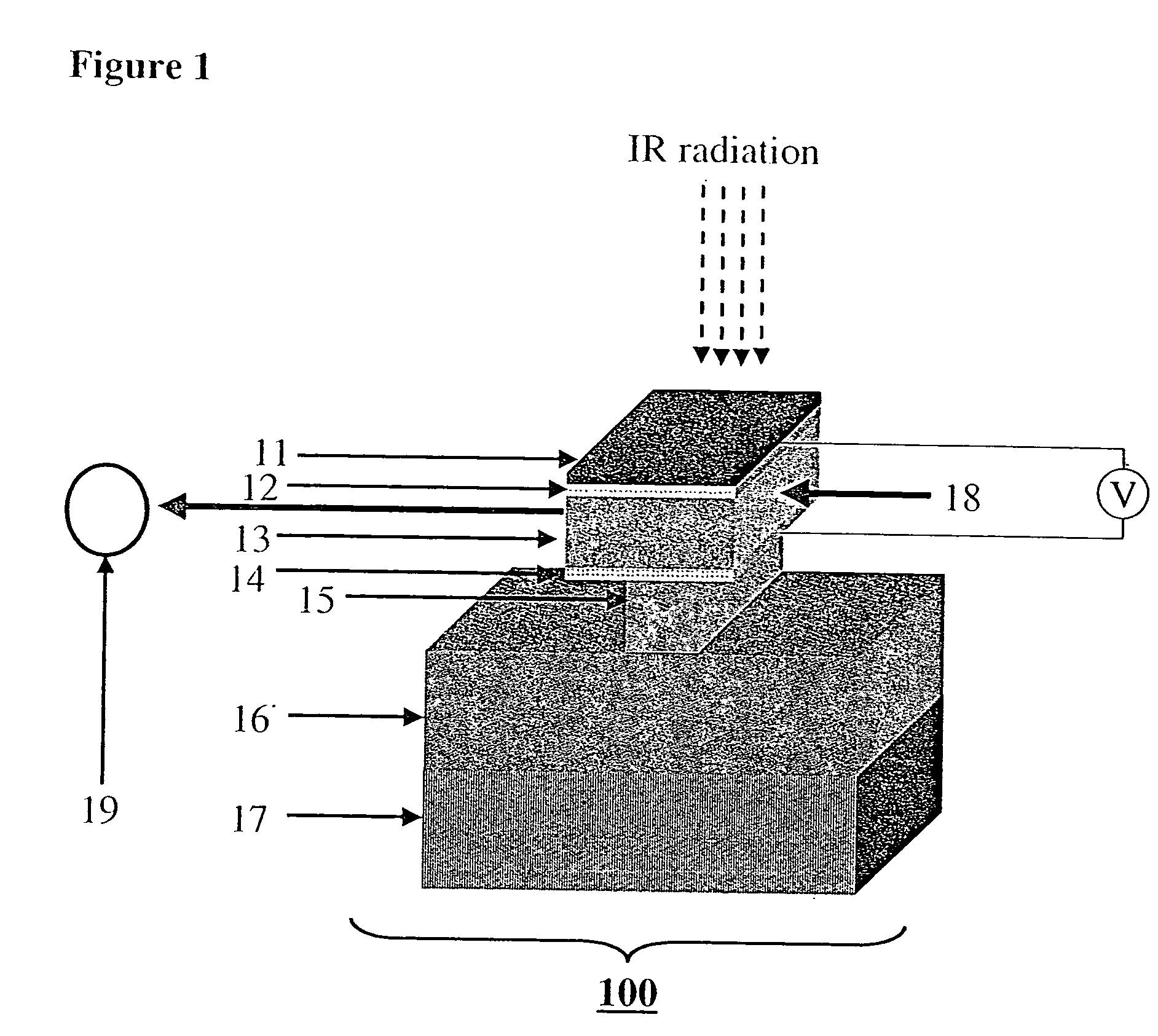
Systems and methods for thermal sensing and imaging using the electro-optic effect. A thermal detection system comprises a temperature sensing element that includes an electro-optic (EO) material layer having a length axis and characterized by a temperature dependent index of refraction, an electrical mechanism for inducing a chance in the index of refraction, a laser beam propagating lengthwise through EO layer for probing the refraction index change, and a light intensity meter for measuring a laser beam intensity change caused by the temperature dependent refraction index change. Thermal imaging is obtained by using a pixel array of such thermal sensing elements. The intensity reading may be done in either a cross-polarizer or a Mach Zehnder Interferometry reading configuration.

Description

FIELD OF THE INVENTION [0001] The present invention relates to remote sensing of heat emitted by bodies, namely, the detection of temperature from a distance by optical means. More specifically, the present invention is of a thermal imaging system and method for detecting thermally induced changes in an electro-optic (EO) material. BACKGROUND OF THE INVENTION [0002] The detection of temperature can in general be performed by a single detector, or by an array of such detectors. A single detector may be used in various applications, e.g. as a motion detector. A detector array is used to yield a thermal picture (image) of the observed scene. Such thermal imaging systems are very useful in night vision (e.g., for military use), as driving aids and in heat measurements (e.g. in fire alarm systems). Thermal detectors are implemented using a number of technologies, some of which (e.g., thermocouples) require direct contact with the measured object, and are therefore unsuitable for long dis...

Claims


Application Information

Patent Timeline
IPC IPC(8): G01J5/00G01NG02F1/01G02F1/03H04N5/33
CPCG02F1/0147H04N5/33G02F1/0327H04N23/23
Inventor SECUNDO, LAVILUBIANIKER, YORAM
Owner NAMAL TECH LTD
Learn More