Methods for producing silicon nitride films and silicon oxynitride films by thermal chemical vapor deposition

a technology of silicon oxynitride and thermal chemical vapor deposition, which is applied in the direction of chemical vapor deposition coating, coating, plasma technique, etc., can solve the problems of poor thermal stability, poor step coverage, and low film density

Active Publication Date: 2005-05-12
LAIR LIQUIDE SA POUR LETUDE & LEXPLOITATION DES PROCEDES GEORGES CLAUDE
View PDF13 Cites 37 Cited by
  • Summary
  • Abstract
  • Description
  • Claims
  • Application Information

AI Technical Summary

Benefits of technology

[0012] As the result of extensive investigations directed to addressing the issues described hereabove, the present inventors found that trisilylamine, aside from its lack of chlorine and carbon, reacts with ammonia to produce high-quality silicon nitride and reacts with ammonia and an oxygen-containing gas to produce high-quality silicon oxynitride. These reactions are also not accompanied by the appearance of reaction by-products downstream from the reaction chamber. The inventors also discovered that the ammonia: trisilylamine feed flow rate ratio into the reaction chamber during the production of silicon nitride film by the reaction of trisilylamine with ammonia influences the compositional stability of the resulting silicon nitride film. The inventors further discovered that the reaction temperature (film formation temperature) during the production of silicon nitride film by the reaction of trisilylamine with ammonia influences the step coverage afforded by the silicon nitride film product. The present invention is based on these discoveries.

Problems solved by technology

The silicon nitride films formed in this manner by PECVD typically do not have a stoichiometric composition and are also hydrogen rich and accordingly exhibit a low film density, a poor step coverage, a fast etching rate, and a poor thermal stability.
However, ammonium chloride is produced as a by-product in the reaction of dichlorosilane and gaseous ammonia in this LPCVD procedure: this ammonium chloride accumulates in and clogs the reactor exhaust lines and also deposits on the wafer.
This problem also occurs when the aforementioned prior art precursors are used to produce silicon oxynitride films (with the same precursors, nitrogen containing gases plus an oxygen containing gas, which are films that have the same properties and applications as silicon nitride films.
However, this article does not go beyond reporting on the silicon nitride growth mechanism, nor does it provide any evaluation of the properties of the produced silicon nitride films.

Method used


Image

  • Methods for producing silicon nitride films and silicon oxynitride films by thermal chemical vapor deposition
  • Methods for producing silicon nitride films and silicon oxynitride films by thermal chemical vapor deposition
  • Methods for producing silicon nitride films and silicon oxynitride films by thermal chemical vapor deposition

Examples


example 1

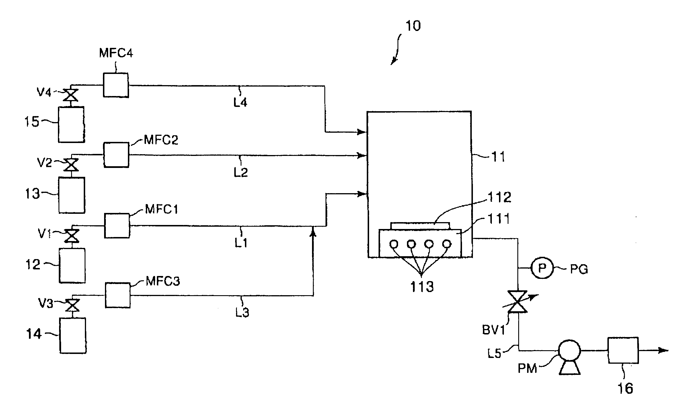
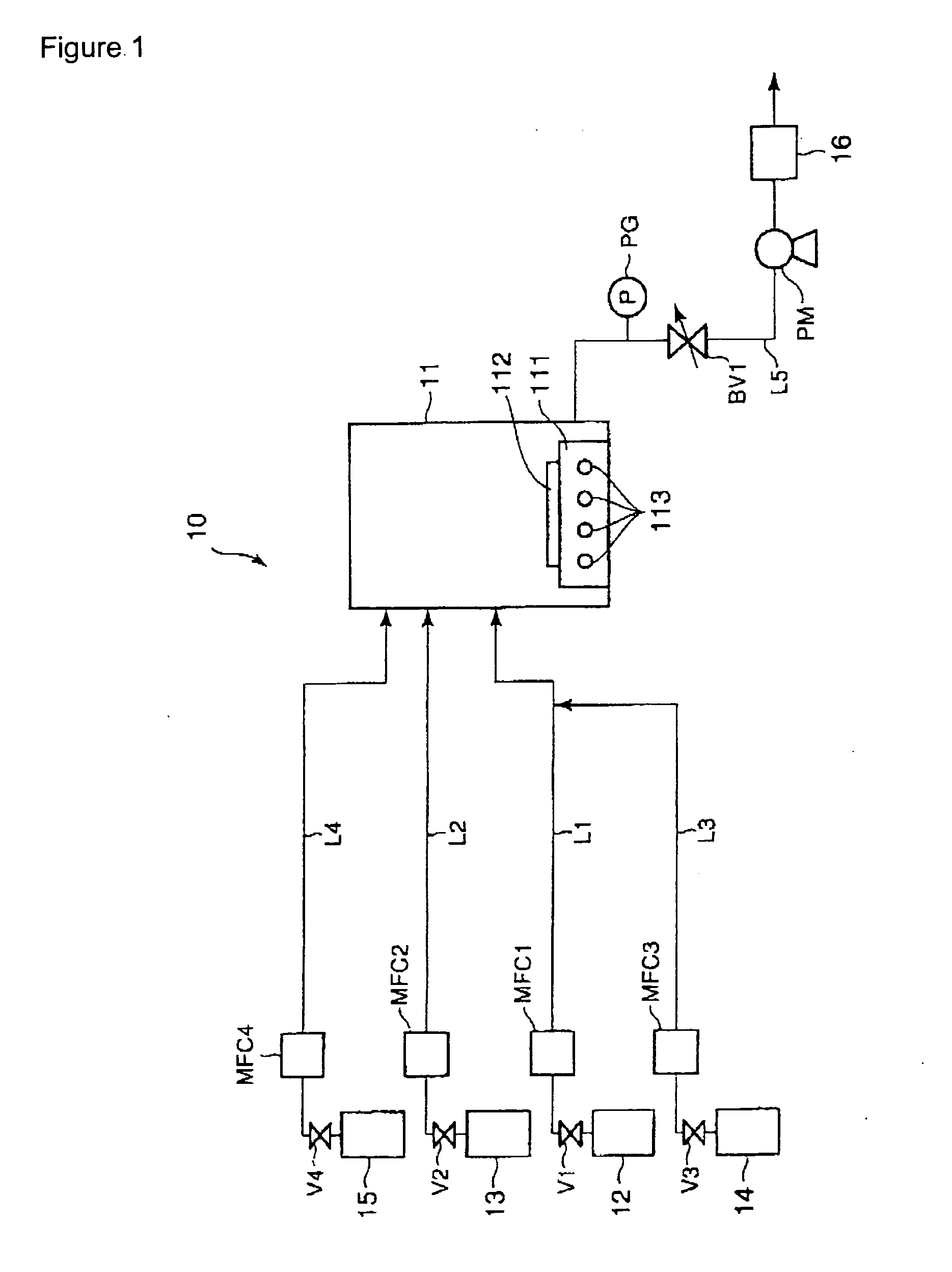
[0080] A production apparatus as illustrated in FIG. 1 (lacking, however, an oxygen source gas feed system) was used in this example. Ammonia gas and TSA gas were introduced into a CVD reaction chamber holding a silicon substrate and a silicon nitride film was formed on this silicon substrate under the following conditions. [0081] ammonia gas flow rate: 40 sccm [0082] TSA gas flow rate: 0.5 sccm [0083] pressure within the CVD reaction chamber: 1 torr [0084] reaction temperature: 640° C.

[0085] The resulting silicon nitride film was confirmed by Auger spectroscopy to have the composition Si0.81N. The deposition (growth) rate of this silicon nitride film was 17 Å / min. The NH3 / TSA flow rate ratio in this example was 80, and a stable film composition was achieved.

example 2

[0086] A production apparatus as illustrated in FIG. 1 (lacking, however, an oxygen source gas feed system) was used in this example. Ammonia gas and TSA gas were introduced into a CVD reaction chamber holding a silicon substrate and a silicon nitride film was formed on this silicon substrate under the following conditions. [0087] ammonia gas flow rate: 40 sccm [0088] TSA gas flow rate: 4 sccm [0089] pressure within the CVD reaction chamber: 1 torr [0090] reaction temperature: 560° C.

[0091] The resulting silicon nitride film was confirmed by Auger spectroscopy to have the composition Si1.04N. The deposition (growth) rate of this silicon nitride film was 6 Å / min. The NH3 / TSA flow rate ratio in this example was 10, and a stable film composition was achieved.

example 3

[0092] A production apparatus as illustrated in FIG. 1 (lacking, however, an oxygen source gas feed system) was used in this example. Ammonia gas and TSA gas were introduced into a CVD reaction chamber holding a silicon substrate, and a silicon nitride film was formed on this silicon substrate using a pressure within the CVD reaction chamber of 1 torr and a reaction temperature of 600° C. Silicon nitride film formation was carried out at different NH3 / TSA flow rate ratios over the range from 0 to 80. Auger spectroscopy was used to analyze the composition of the silicon nitride films obtained at the different NH3 / TSA flow rate ratios, and the compositional variation rate was calculated from the equation

compositional variation rate=−d(Si / N)dX

wherein X is the NH3 / TSA flow rate ratio. The results are reported in FIG. 3.

[0093] The results reported in FIG. 3 show that the film compositional variation rate due to changes in the flow rate ratio assumed very small values when the NH3 / TSA...


PUM

PropertyMeasurementUnit
temperatureaaaaaaaaaa
temperaturesaaaaaaaaaa
pressuresaaaaaaaaaa

Abstract

Silicon nitride film is formed on substrate (112) by feeding trisilylamine and ammonia into a CVD reaction chamber (11) that contains a substrate (112). The ammonia gas/trisilylamine gas flow rate ratio is set to a value of at least about 10 and/or the thermal CVD reaction is run at a temperature no greater than about 600° C. Silicon oxynitride is obtained by introducing an oxygen source gas into the CVD reaction chamber (11). This method avoids the production of ammonium chloride and/or the incorporation of carbonaceous contaminants which are detrimental to the quality of the deposited film.

Description

BACKGROUND OF THE INVENTION [0001] 1. Field of the Invention [0002] This invention relates to methods for producing silicon nitride films and silicon oxynitride films. More particularly, this invention relates to methods for producing silicon nitride films and silicon oxynitride films by thermal chemical vapor deposition (thermal CVD). [0003] 2. Description of the Prior Art [0004] Silicon nitride films have excellent barrier properties and an excellent oxidation resistance and as a consequence are used in the fabrication of semiconductor devices, for example, as an etch-stop layer, barrier layer, or gate dielectric layer, and in oxide / nitride stacks. [0005] Plasma-enhanced CVD (PECVD) and low-pressure CVD (LPCVD) are the methods primarily used at the present time to form silicon nitride films. [0006] PECVD is typically carried out by introducing a silicon source (typically silane) and a nitrogen source (typically ammonia, but more recently nitrogen) between a pair of parallel plate ...

Claims


Application Information

Patent Timeline
Patent Type & Authority Applications(United States)
IPC IPC(8): C23C16/42C23C16/30C23C16/34H01L21/314H01L21/318
CPCC23C16/308C23C16/345H01L21/0214H01L21/3185H01L21/02219H01L21/02271H01L21/3145H01L21/0217
Inventor DUSSARRAT, CHRISTIANGIRARD, JEAN-MARCKIMURA, TAKAKOTAMAOKI, NAOKISATO, YUUSUKE
Owner LAIR LIQUIDE SA POUR LETUDE & LEXPLOITATION DES PROCEDES GEORGES CLAUDE
Why Eureka
Try Eureka