
Fabrication of drug loaded biodegradable polymer fibers

a biodegradable polymer fiber and drug technology, applied in the field of tissue engineering, can solve the problems of large scaffolds that cannot be used, small scaffolds, and no way to ensur

Inactive Publication Date: 2005-05-19
BOARD OF RGT THE UNIV OF TEXAS SYST
View PDF9 Cites 115 Cited by
  • Summary
  • Abstract
  • Description
  • Claims
  • Application Information

AI Technical Summary

Benefits of technology

"The present invention provides a scaffold for growing cells that can be used in both in vitro and in vivo. The scaffold is made up of biodegradable polymer fibers that can be controlled to release therapeutic agents at specific locations and at specific times. The fibers can be distributed in a non-homogeneous pattern, meaning that the therapeutic agents can be delivered in a controlled and specific way. The scaffold can be woven, non-woven, braided, or knitted, and can contain one or more therapeutic agents that vary in concentration along the fibers. The scaffold can also be designed to release the therapeutic agents in a controlled and specific way over time."

Problems solved by technology

The difficulty with this approach is the scaffolding must be small, as no cell can survive more than a couple millimeters away from a source of oxygen and nutrients.
Therefore, large scaffolds cannot be used, as the scaffold will not vascularize adequately in time to save the cells in the interior regions.
A major problem is that there is currently no way to ensure that the appropriate cell types will migrate into the scaffold, and that the mechanical and biological properties will be maintained to provide the patient's physiological need.
In both of the above approaches, the scaffold may be biodegradable, meaning that over time it will break down both chemically and mechanically.
Currently it is not possible to faithfully reproduce a biologically active extracellular matrix.
Because cells must be close to a source of oxygen and nutrients in order to survive and function, a major current limitation is that of blood supply.
Most current methodologies provide no specific means of actively assisting the incorporation of blood vessels into and throughout the polymer matrix.
This places limitations on the physical size and shape of the polymer matrix.

Method used

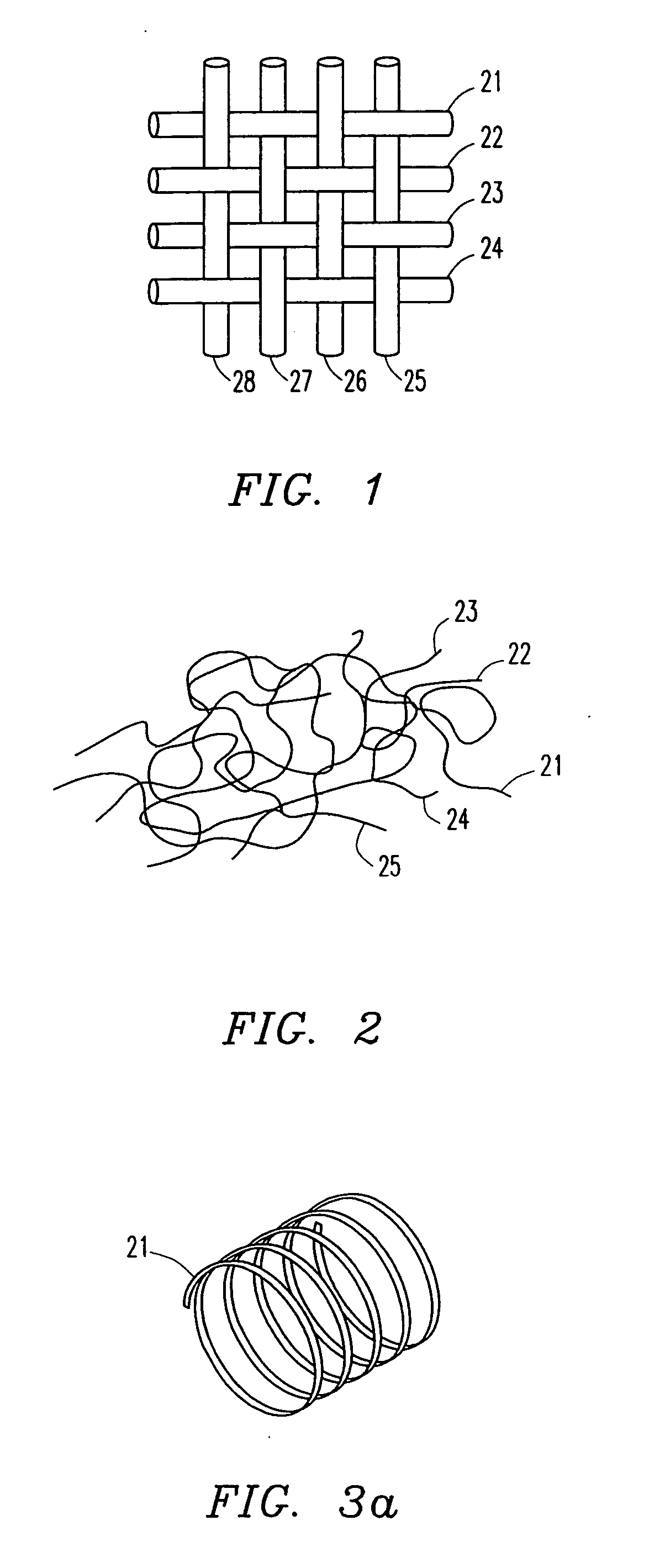

Image

  • Fabrication of drug loaded biodegradable polymer fibers
  • Fabrication of drug loaded biodegradable polymer fibers
  • Fabrication of drug loaded biodegradable polymer fibers

Examples


example 1

Fabrication of Polymer Fibers Containing Therapeutic Agents

[0080] In one embodiment of the present invention, the following procedure is used to create the drug-releasing fibers. The apparatus is depicted in FIG. 8. First, a biodegradable polymer such as poly(L-lactic acid) (PLLA), poly(DL-lactic acid), polycaprolactone, poly(glycolic acid), polyanhydride, or copolymers or blends of these or other biodegradable polymers are dissolved in some appropriate solvent (A) at concentrations ranging from 5 to 30 wt % depending on the type of polymer, 10 wt % being preferred for PLLA. In this embodiment, solvent (A) has low miscibility with water, and is very miscible with the coagulation bath solvent (B). Preferred choices of solvent (A) include chloroform and methylene chloride. Once the polymer is dissolved, an aqueous solution containing both the biomolecules(s) of interest and a surfactant, is added to the polymer solution. The concentration of the aqueous emulsion is typically in the r...

example 2

Fabrication of Polymer Fibers Containing Variable Concentrations of Therapeutic Agents

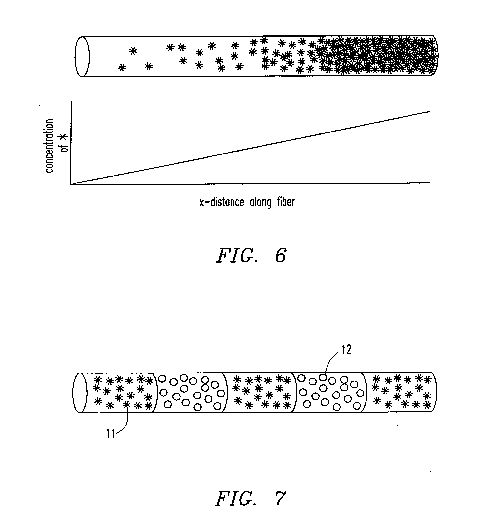
[0091] In another fabrication embodiment, the process is similar to that described in Example 1, with the exception that a concentration gradient is applied down the length of the fiber. This is accomplished by having two solutions. One is a polymer emulsion containing the therapeutic agent(s) of interest, and the other does not contain therapeutic agents, or contains different biomolecules. The gradient is accomplished by continuously changing the ratio of the two solutions during the extrusion process. This can be accomplished in a number of ways including a butterfly valve at a “Y” junction as shown in FIG. 13, or using independent pumps with or without a mixing chamber as shown in FIG. 14. In this way, a well-controlled gradient is established with known change in concentration per centimeter length. Another embodiment of the present invention is the creation of “banded” fibers. In banded fibe...

example 3

Fabrication of Polymer Fibers with Concentric Coatings

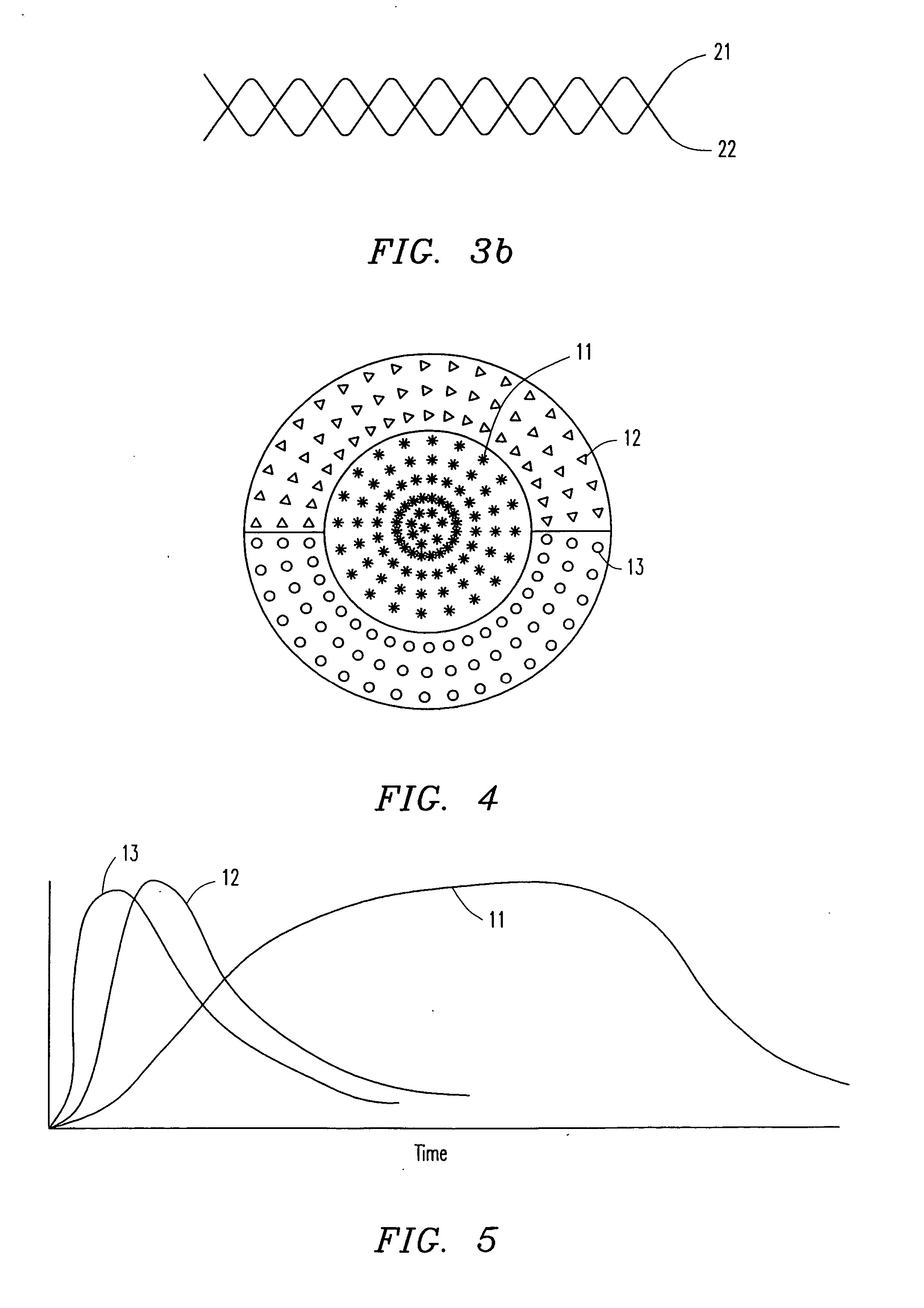
[0093] In yet another fabrication embodiment, a pre-existing fiber is loaded through a spinneret and through the coagulation bath. The liquid polymer emulsion is added in a “T” or “Y” junction and coats the fiber before entering a coagulation bath. Thus concentric coatings are applied to the fiber, with each coating having the ability to contain a different therapeutic agent(s) as shown in FIG. 4. The coating polymer may be the same or different from the core polymer. There may be molecules attached to the core fiber to increase the adhesion of the coating polymer. For example, a thin layer of BSA, may improve the adhesion of chitosan to poly(L-lactic acid). By an intricate spinneret, two or more polymer emulsions each containing a different biomolecule can be put in the coating. This is accomplished by bringing all coating materials into the spinneret, with baffles separating each coating polymer stream. This allows fibers to r...


PUM

PropertyMeasurementUnit
distanceaaaaaaaaaa
distanceaaaaaaaaaa
diameteraaaaaaaaaa

Abstract

The invention provides tissue engineering compositions and methods wherein three-dimensional matrices for growing cells are prepared for in vitro and in vivo use. The matrices comprise biodegradable polymer fibers capable of the controlled delivery of therapeutic agents. The spatial and temporal distribution of released therapeutic agents is controlled by use of defined nonhomogeneous patterns of therapeutic agents in the matrices.

Description

[0001] The present invention claims priority to provisional application Ser. No. 60 / 147,827, filed Aug. 6, 1999.BACKGROUND OF THE INVENTION [0002] 1. Field of the Invention [0003] This invention relates to the field of medicine and tissue engineering, and in particular to drug releasing biodegradable implants. [0004] 2. Description of Related Art [0005] Tissue engineering is a discipline wherein living cells are used to replace functional loss because of injury, disease, or birth defect in an animal or human. These replacement cells can be autologous, allogenic, or, in limited circumstances, xenogenic. The field of tissue engineering is a new area of medicine and optimal procedures have yet to be elucidated. [0006] At present, there are several primary avenues investigators are using to engineer tissues. One is to harvest cells from a healthy donor, preferably from the same individual, or at least from an appropriate donor of the same species, and grow those cells on a scaffold in v...

Claims


Application Information

Patent Timeline
Patent Type & Authority Applications(United States)
IPC IPC(8): A61K9/00A61K9/70A61K31/7088A61K38/00A61K47/34A61K47/36A61L27/00A61L27/54A61L27/58A61P7/00A61P35/00A61P37/02D01F1/10D01F6/62D01F8/14D06M15/03D06M16/00
CPCA61B17/1128Y10T428/30A61K9/0051A61K9/70A61L27/54A61L27/58A61L2300/252A61L2300/258A61L2300/414A61L2300/426A61L2300/604D01F1/10D01F6/625D01F8/14D06M15/03D06M16/00A61K9/0024Y10T442/2525A61P35/00A61P37/02A61P43/00A61P7/00
Inventor NELSON, KEVINROMERO-SANCHEZ, ANDRES A.SMITH, GEORGE M.ALIKACEM, NADIRRADULESCU, DELIAWAGGONER, PAULAHU, ZHIBING
Owner BOARD OF RGT THE UNIV OF TEXAS SYST
Learn More