Process for welding

a welding process and process technology, applied in the direction of welding/cutting media/materials, welding apparatus, manufacturing tools, etc., can solve the problems of unproductive causation factor, inability to achieve successful welding of such workpieces, and in particular workpieces made of carbon steel, and achieve the effect of improving the life of the electrod

Inactive Publication Date: 2005-05-26
JV IND CO LLC
View PDF10 Cites 95 Cited by
  • Summary
  • Abstract
  • Description
  • Claims
  • Application Information

AI Technical Summary

Benefits of technology

[0026] The electrode compositions described above may be used without the use of the shield gas delivery hose material described above for enhanced electrode life when carrying out the basic process of welding in accordance with U.S. Pat. No. 5,686,002.

Problems solved by technology

Successful welding of such workpieces, in particular workpieces made of carbon steel, was originally doubtful due to constraints against allowing hydrogen into carbon steel weldments because of embrittlement and porosity problems encountered in prior art welding procedures used with such metals when hydrogen contamination occurred.
Specifically, when the second weld pass was made over the root pass, sudden virtually explosive eruptions of fused metal in the weld pool area occurred with sufficient frequency and intensity so as to interrupt the welding process by contaminating the electrode and gas lens of the GTAW torch equipment.
Electrodes were suspect initially, but that proved to be unproductive as a causation factor.
Yet, the presence of small pockets of mostly argon and minor quantities of free hydrogen hardly would account for the violent nature of the eruptions that were observed during the first filler pass over the root weldment.
There simply was insufficient oxygen to combine with the little hydrogen in the shield gas that was not consumed during welding to create moisture in the weld metal, irrespective of possible occurrence of cells or pockets in the weld metal due to other causes.
Still the source of such elements eluded discovery.
Upon heating during the subsequent weld pass, the moisture was superheating and creating the violent expulsion effects observed.
As a secondary factor, the tungsten electrodes conventionally used in GTAW equipment were observed to degrade severely during use in the welding process according to U.S. Pat. No. 5,686,002, that is using 95 / 5 argon-hydrogen gas mixture.
On the other hand, tungsten electrodes used during a welding process according to the U.S. Pat. No. 5,686,002 patent with carbon, chrome-molybdenum and other non-stainless steels exhibited or will be expected to exhibit shorter life and to require replacing at frequent intervals, possibly due to longer welding times, higher heat input due to the hydrogen in the shield gas, oxide condensation on the electrodes, weld zone contamination at the location of the electrodes and other unidentified causes.

Method used


Image

  • Process for welding
  • Process for welding

Examples


Embodiment Construction

[0027] With reference to the appended drawings:

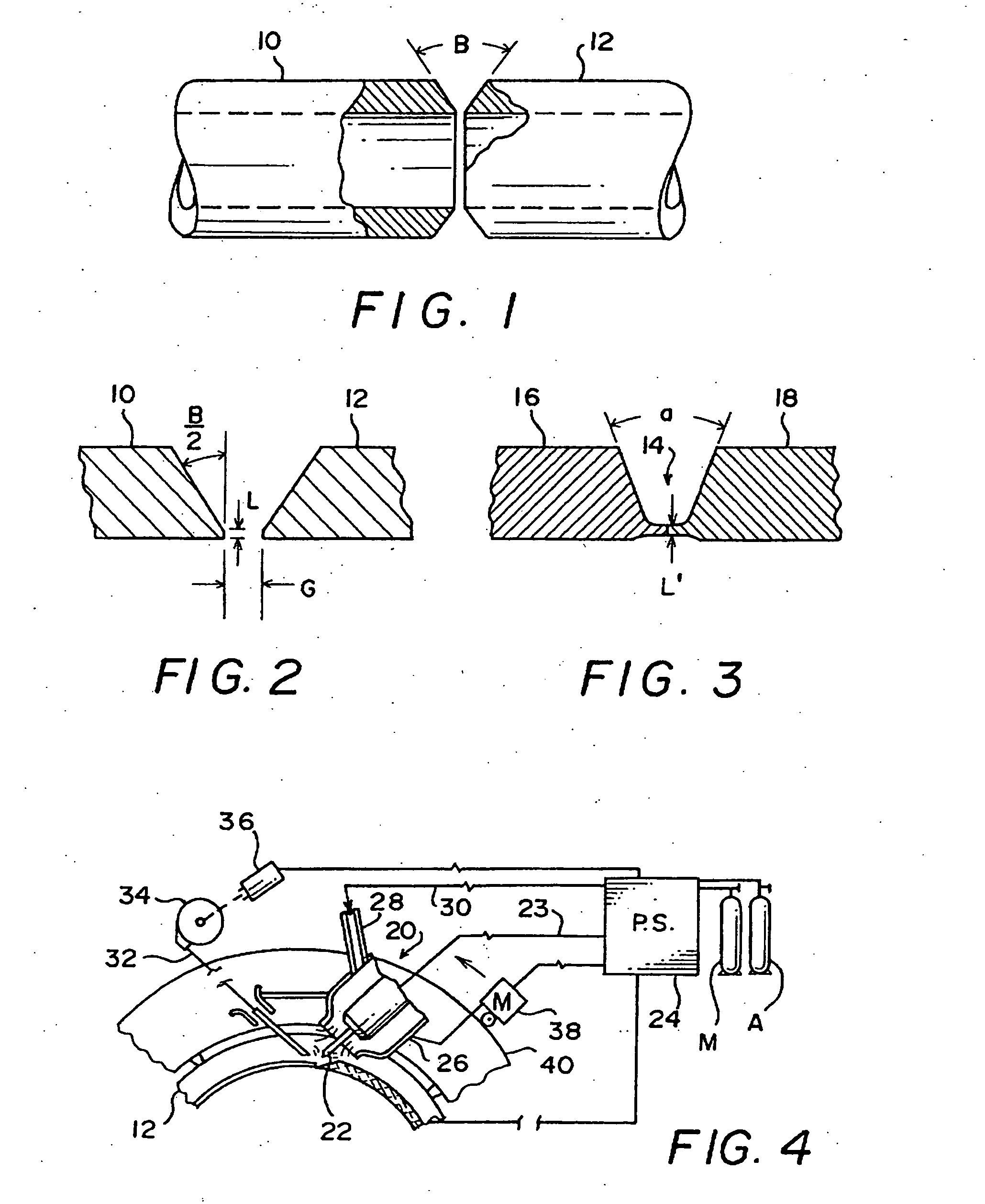
[0028]FIG. 1 schematically illustrates a pair of non-stainless steel tubular workpieces to be buttwelded having beveled end joint preparations and an open root gap ready for carrying out a welding procedure in accordance with the prior art;

[0029]FIG. 2 is an enlarged view of the beveled joint area between the tubular workpieces illustrated in FIG. 1;

[0030]FIG. 3 shows a “J-type” joint preparation conventionally used for buttwelding with GTAW equipment; and

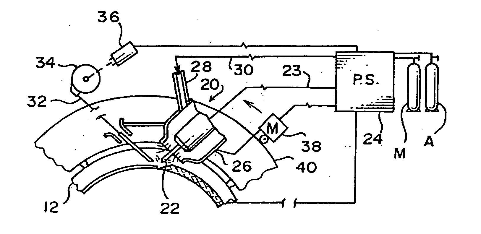
[0031]FIG. 4 schematically shows a welding procedure in accordance with the prior art being carried out using orbital GTAW equipment supplied with filler wire and both an argon-hydrogen shield gas mixture and argon gas alone.

DETAILED DESCRIPTION OF PREFERRED EMBODIMENTS OF THE INVENTION

[0032] In accordance with a prior art process as described in U.S. Pat. 5,686,002, and with reference to the drawings, non-stainless steel (e.g., carbon steel) metal workpieces 10, 12 to be buttweld...


PUM

PropertyMeasurementUnit
thicknessesaaaaaaaaaa
compression stressaaaaaaaaaa
areaaaaaaaaaaa

Abstract

A welding process for non-stainless steel workpieces using GTAW equipment and hydrogen containing shield gas on a first root pass is improved by using a shield gas delivery system comprising hoses or conduits made of elastomeric material having a moisture permeability coefficient of less that 275, preferably less than 100, and using a tungsten electrode composition comprising at least tungsten and lanthanum oxide, and preferably tungsten, lanthanum oxide, yttrium oxide and zirconium oxide. Preventing moisture permeation through the elastomeric hoses delivering hydrogen containing shield gas eliminates expulsion of fused weld metal during second pass filler welding over the root pass weld. Electrode life is enhanced using the tungsten compounds.

Description

BACKGROUND [0001] 1. Field [0002] This invention relates to a welding process, in particular a shielded gas tungsten arc welding (GTAW) process. [0003] 2. Related Art [0004] An improved welding process for butt welding steel workpieces along bevel prepared joints using GTAW equipment with filler wire and hydrogen-argon (or other inert gas) shield gas mixtures during the first or root pass and then hydrogen-free inert gas during the subsequent filler passes is disclosed in U.S. Pat. No. 5,686,002 issued Nov. 11, 1997, this patent owned in common with the invention described and claimed herein. [0005] In accordance with the process described in U.S. Pat. No. 5,686,002, medium to thick sheet or tubular steel metal workpieces are prepared by beveling their edges to be joined so they butt against each other with a small clearance (“open root”). A root weld pass is then made using conventional automatic (including semi-automatic) or non-automated GTAW equipment, filler wire and a shield g...

Claims


Application Information

Patent Timeline
Patent Type & Authority Applications(United States)
IPC IPC(8): B23KB23K9/167B23K9/32B23K35/22B23K35/38
CPCB23K9/167B23K35/383B23K35/222B23K9/324
Inventor FLOOD, DALE A.
Owner JV IND CO LLC
Why Eureka
Try Eureka