Multilayer organic photodetectors with improved performance

a photodetector and multi-layer technology, applied in the field of organic photodetectors, can solve the problems of high quantum efficiency, undesirable outcomes in photosensitive optoelectronic devices, and device configuration predictions from donor/acceptor criteria may not be borne out by actual device performance, so as to reduce the dark current and reduce the dark current. , the effect of reducing the energy barrier for electron injection

Active Publication Date: 2005-05-26
THE TRUSTEES FOR PRINCETON UNIV
View PDF10 Cites 247 Cited by
  • Summary
  • Abstract
  • Description
  • Claims
  • Application Information

AI Technical Summary

Benefits of technology

[0012] The present invention provides organic-based photodetectors having a reduced dark current. The dark current may be reduced (i) by the use of a high work function anode, (ii) by the use of electron donor layer and the electron acceptor layer that provide a high energy barrier for electron injection from the anode into the electron acceptor layer, and/or (iii) by placing a thick donor layer adjacent to the anode.
[0013] In one embodiment, the invention provides an organic photodetector comprising a high work function anode, an active region an exciton blocking layer, and a cathode. The active region comprises one or more subcells in series, wherein each subcell comprises an organic electron donor layer and an organic electron acceptor layer, and wherein the thicknesses of the organic electron donor layer and the organic electron acceptor layer are low enough to allow tunneling. Preferably, the anode comprises a material having a work function greater than about 4.6 eV.
[0014] In another embodiment, the invention provides an organic photodetector comprising an

Problems solved by technology

The low indices of refraction of the organic materials and their corresponding transparent substrates (glass or plastics) also allow for efficient light coupling into devices, leading to potentially high quantum efficiencies.
Either of these outcomes is undesirable in a photosensitive

Method used


Image

  • Multilayer organic photodetectors with improved performance
  • Multilayer organic photodetectors with improved performance
  • Multilayer organic photodetectors with improved performance

Examples


example 1

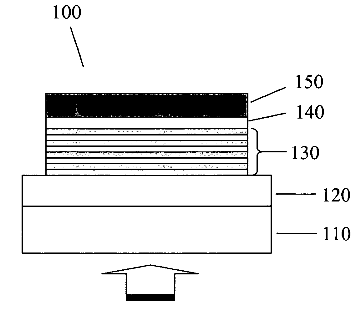
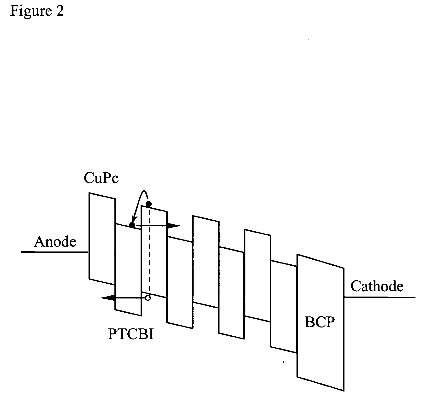
[0088] Devices having the general structure ITO / (CuPc / PTCBI)N / BCP 150 Å / Al 1000 Å were constructed. A 1500-Å-thick transparent, conducting ITO layer (sheet resistance ˜30 Ω / □) commercially precoated on a glass substrate serves as the anode [Applied Film Corp., 6797-T Winchester Circle, Boulder, Colo. 80301]. The substrate was cleaned in boiling trichloroethylene, acetone and boiling isopropanol before being loaded into an ultrahigh vacuum (UHV) organic molecular beam deposition (OMBD) [S. R. Forrest, Chem. Rev. 97, 1793 (1997)] chamber with a base pressure of 1×10⁻¹⁰ Torr. The active region of the photodetector consisting of alternating layers of CuPc and PTCBI was grown by OMBD at a rate of 0.3 to 0.4 Å / s at room temperature, followed by a 150-Å-thick BCP exciton-blocking layer. The thicknesses of the individual CuPc and PTCBI layers, xD and xA, respectively, were varied from 15 Å to 240 Å, and the number of CuPc / PTCBI bilayer periods, N, was varied from 16 to 1 accordingly, to mai...

example 2

[0108] Devices having the general structure ITO / (CuPc / PTCBI)N / BCP 150 Å / Al 1000 Å were constructed. The active region, disposed between an ITO anode and a metal cathode, consists of alternating layers of donor-like CuPc and acceptor-like 3,4,9,10-PTCBI, with the first CuPc layer in contact with the anode. A 150-Å-thick layer of BCP was deposited on top of the active region to serve as an exciton blocking layer. All the organic layers were deposited by the ultrahigh vacuum (UHV) process of organic molecular beam deposition (OMBD) at a rate of 0.3 to 0.4 Å / s at room temperature. The 1000-Å-thick Al cathode was deposited by thermal evaporation through a shadow mask with 1 mm diameter openings in a separate vacuum chamber with a base pressure of −6 Torr.

[0109] Two types of ITO films were used as the anodes of multilayer organic photodetectors: 1500-Å-thick ITO films with a sheet resistance of 30 Ω / □ commercially precoated on glass substrates [Applied Film Corp., 6797-T Winchester Circl...


PUM


Abstract

The present invention generally relates to organic photodetectors. Further, it is, directed to an optimized organic photodetector having reduced dark current and high efficiency and response time.

Description

FIELD OF THE INVENTION [0001] The present invention generally relates to organic photodetectors. More specifically, it is directed to organic photodetectors having a reduced dark current. BACKGROUND [0002] Small molecular weight organic materials have found a wide range of optoelectronic applications in the past two decades due to their advantages such as being lightweight, cost effective and compatible with flexible substrates. [S. R. Forrest, IEEE J. Sel. Top. Quantum Electron. 6, 1072 (2000)]. The broad absorption spectra and high absorption coefficients (˜105 cm−1), as well as the chemists' ability to tailor the electronic and optoelectronic properties to suit a particular application or spectral range, make organic materials of particular interest for application to photodetection [P. Peumans, V. Bulovic, and S. R. Forrest, Appl. Phys. Lett. 76, 3855 (2000); P. Peumans, A. Yakimov, and S. R. Forrest, J. Appl. Phys. 93, 3693 (2003)] and solar energy conversion [P. Peumans, A. Ya...

Claims


Application Information

Patent Timeline
IPC IPC(8): H01L21/00H01L27/30H01L31/06H01L35/24H01L51/00H01L51/42
CPCH01L27/305H01L51/0053H01L51/0071Y02E10/549H01L51/424H01L51/4246H01L2251/308H01L51/0078H10K39/30H10K85/621H10K85/311H10K85/657H10K30/20H10K30/211H10K2102/103
Inventor FORREST, STEPHEN R.XUE, JIANGENG
Owner THE TRUSTEES FOR PRINCETON UNIV
Why Eureka
Try Eureka