Implantable biofuel cell system based on nanostructures

a biofuel cell and nanostructure technology, applied in the direction of indirect fuel cells, non-aqueous electrolyte cells, cell components, etc., can solve the problems of defective sinoatrial nodes, inability to maintain a regular heartbeat, and devices that are too large to be implanted inside the human body, and achieve the effect of high power

Inactive Publication Date: 2005-06-02
NANOSOLUTIONS
View PDF6 Cites 106 Cited by
  • Summary
  • Abstract
  • Description
  • Claims
  • Application Information

AI Technical Summary

Benefits of technology

[0020] The present invention is directed to a bio-implantable electrochemical cell system for providing high power for active implantable medical devices. The electrochemical cell of the present invention provides an order of magnitude improvement in power density (1,000 to 10,00...

Problems solved by technology

The first cardiac pacemaker was invented by John Hopps in 1950, but this device was far too large to be implanted inside the human body.
Patients having these heart pacing abnormalities have a defective sinoatrial node and are unable to maintain a regular heartbeat.
Most cardiac pacemakers use implantable lithium batteries that are implanted with the pacemaker; however, they have the disadvantage of requiring an additional surgery every 24 months to replace the battery.
Constant or variable rates of infusion are possible over long periods of time with minimal human intervention; however, in the case of programmable drug infusion pumps, the battery must eventually be replaced.
At the same time, the size and weight of the power sources for these devices have not been proportionally reduced, primarily due to the difficulty of miniaturizing the case and seal of the power source.
At the same time, the case and seal are neces...

Method used


Image

  • Implantable biofuel cell system based on nanostructures
  • Implantable biofuel cell system based on nanostructures
  • Implantable biofuel cell system based on nanostructures

Examples


Embodiment Construction

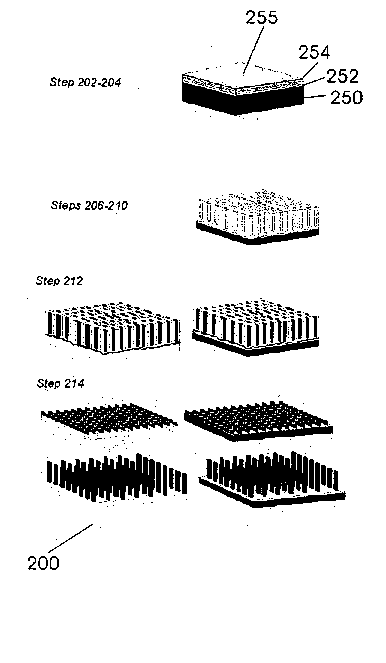
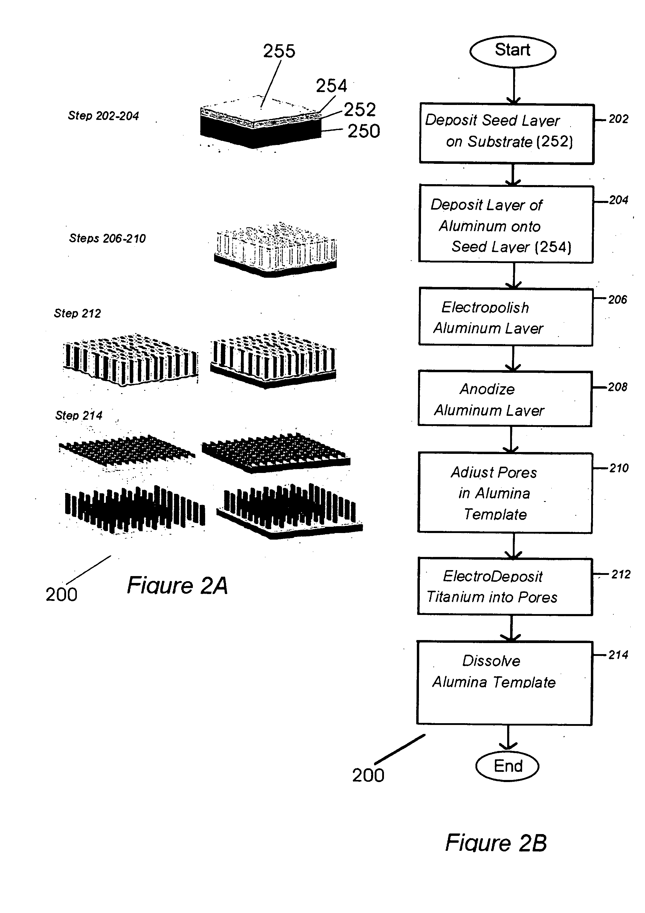
[0051] The following exemplary discussion focuses on a bio-implantable electrochemical cell system for providing high power for active implantable medical devices. The apparatus of the present invention provides an order of magnitude improvement in power density (1,000 to 10,000 μW cm−2) over existing glucose / oxygen fuel cells, with a total output power of 1,000 to 10,000 μW.

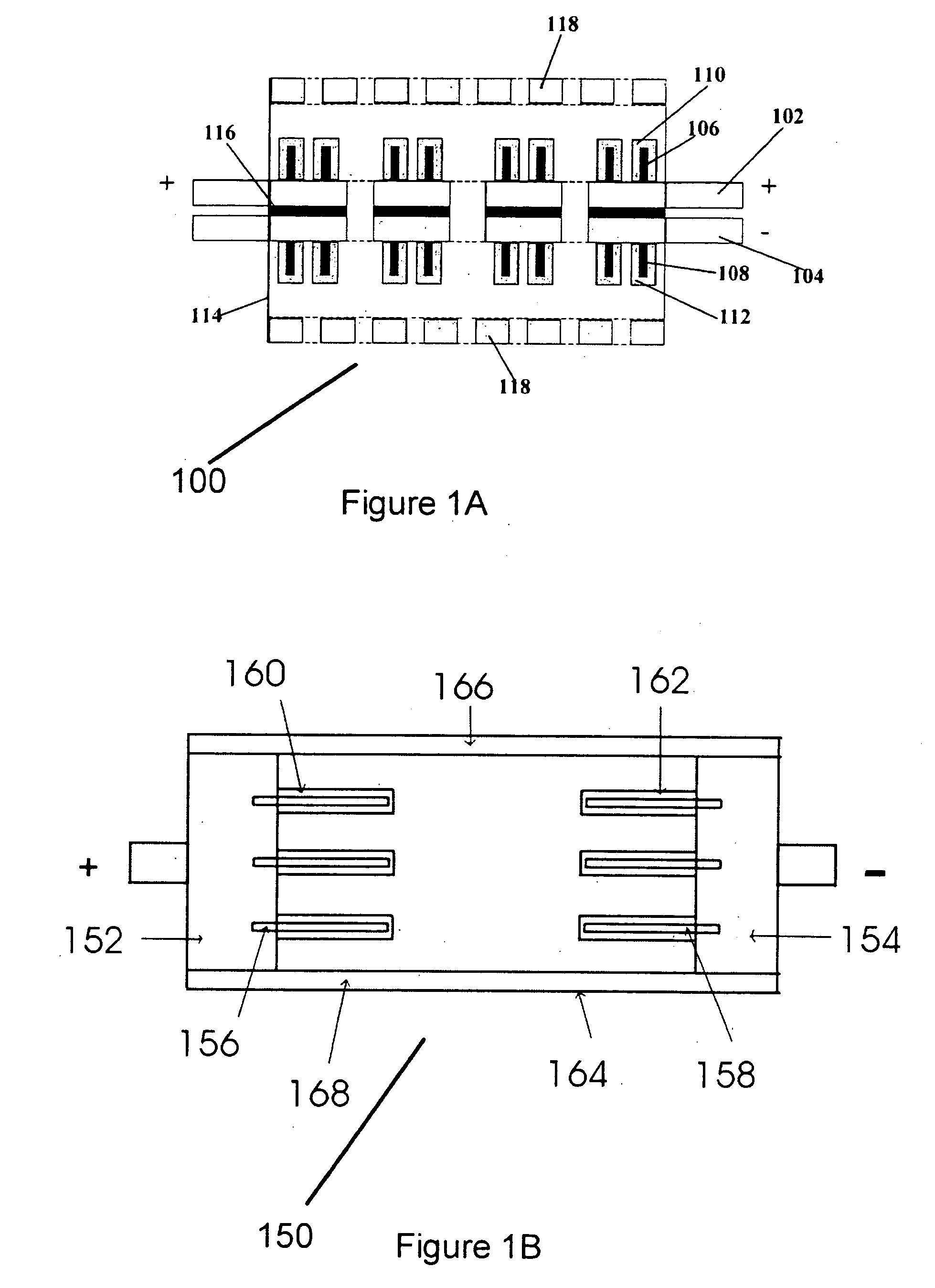
[0052] Referring to FIG. 1A, a first configuration of a single electrochemical cell 100 constructed in accordance with the principles of the present invention, is shown. Electrochemical cell 100 comprises an anode 102 and a cathode 104, both including arrays of nanostructured rods 106 and 108 in their respective interior portions. Immobile enzyme layers 110 and 112 are deposited on the interior surfaces of anode 102 and cathode 104, respectively, including on the arrays of nanostructured rods 106 and 108. Immobile enzyme layer 110 comprises glucose oxidase and is deposited on the interior surface and nanostruct...


PUM


Abstract

A bio-implantable electrochemical cell system for active implantable medical devices. In one embodiment, the fuel cell includes an electrode structure consisting of immobilized anode and cathode enzymes deposited on nanostructured high-surface-area metal nanowires or carbon nanotube electrodes. The anode enzyme comprises immobilized glucose oxidase and the cathode enzyme comprises immobilized laccase. Glucose is oxidized at the surface of the anode and oxygen is reduced at the surface of the cathode. The coupled glucose oxidation-oxygen reduction reactions provide a self-generating current source. In another embodiment, the nanowires or carbon nanotubes, along with the adjacent surface anode and cathode electrodes, are coated with immobilized glucose oxidase and immobilized laccase containing biocolloidal substrates, respectively. This results in the precise construction of an enzyme architecture with control at the molecular level, while increasing the reactive surface area and corresponding output power by at least two orders of magnitude.

Description

BACKGROUND OF THE INVENTION [0001] 1. Field of the Invention [0002] The present invention relates to implantable power sources, and more particularly to a bio-implantable electrochemical cell system for providing high power for active implantable medical devices. [0003] 2. Description of the Prior Art [0004] Implantable power sources for cardiac pacemakers, defibrillators, implantable diffusion pumps, neurostimulators and other active implantable medical devices have contributed to the health of millions of patients during the past few decades. During this same period, there have been increasing pressures to reduce healthcare costs by reducing hospital and in-patient stays without compromising the quality of patient care. The result has been an increase in the numbers of out-patients who rely on active implantable medical devices to maintain and / or improve their health. [0005] An active implantable medical device is defined as any active device which is intended to be totally or par...

Claims


Application Information

Patent Timeline
IPC IPC(8): H01M4/88H01M4/90H01M4/96H01M8/16H01M8/20
CPCB82Y30/00Y02E60/527H01M8/16H01M4/96Y02E60/50
Inventor CHOI, SUNG HOI
Owner NANOSOLUTIONS
Why Eureka
Try Eureka