Ion storage device

Inactive Publication Date: 2005-06-16
SHIMADZU CORP
View PDF2 Cites 20 Cited by
  • Summary
  • Abstract
  • Description
  • Claims
  • Application Information

AI Technical Summary

Benefits of technology

[0019] In the present invention, the LC resonant circuit of the ion storage device includes switching means and resistance means, where the switching means is used to stop the RF voltage when ions are ejected from the ion storing space. Since the inductance L, the capacitance C and the effective resistance R substant

Problems solved by technology

However, actual switching devices 46 and 47 use semiconductor elements such as MOSFETs, which are difficult to flow a large current, or diffic

Method used


Image

  • Ion storage device
  • Ion storage device
  • Ion storage device

Examples


embodiment 1

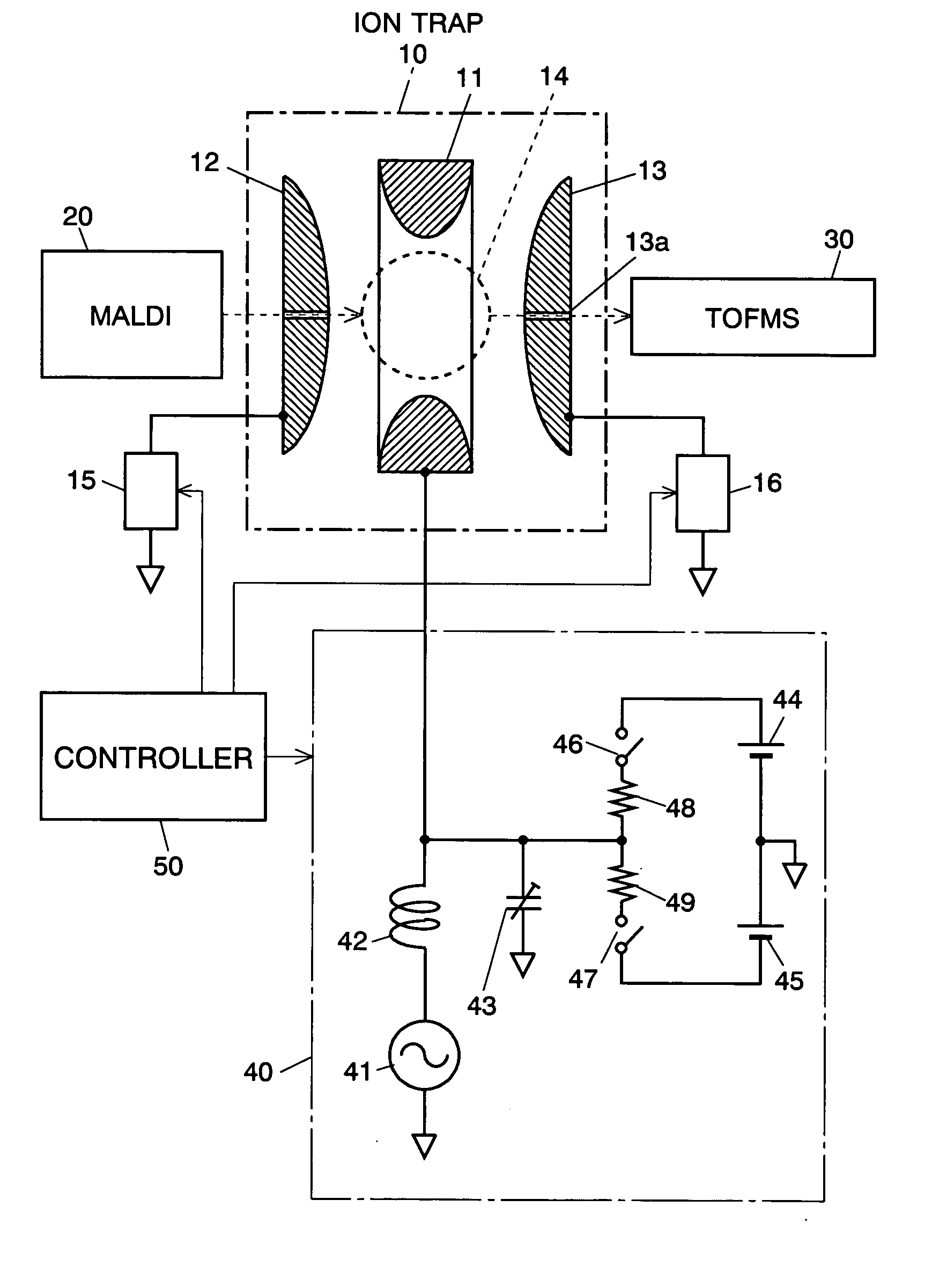
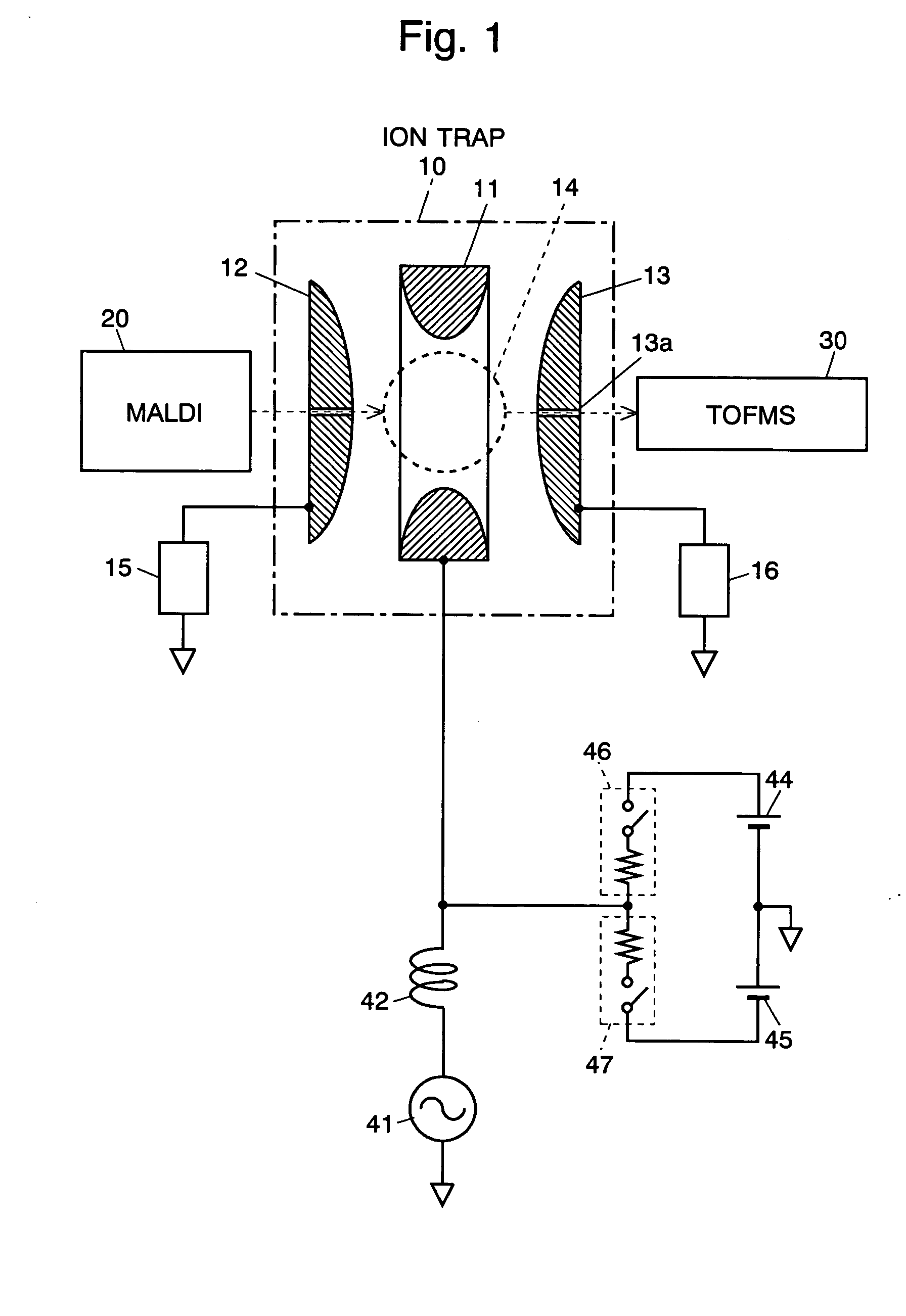
[0034] An ion storage device embodying the present invention is described. FIG. 3 shows the main part of a mass spectrometer using an ion trap 10 as the ion storage device. The ion trap 10 is composed of a ring electrode 11 and a pair of opposing end cap electrodes 12 and 13 with the ring electrode 11 between them. An RF voltage generated in the RF driver circuit 41 is applied to the ring electrode 11, so that a quadrupole electric field is generated in the space surrounded by the electrodes 11, 12 and 13, and an ion storing space 14 is formed there. End cap voltage generators 15 and 16 are respectively connected to the end cap electrodes 12 and 13, which applies appropriate voltages to them at appropriate periods of an analysis.

[0035] When, for example, ions generated in an ion source 20 using MALDI (Matrix-Assisted Laser Desorption / Ionization) are injected into the ion trap 10, appropriate voltages for decreasing the energy of the ions are applied to the end cap electrodes 12 and...

embodiment 2

[0042] In the above embodiment 1, two switching devices and two resistances are used to perform the function of the present invention. FIG. 4 shows another embodiment (Embodiment 2), in which a switching device 51 and a resistance 52 realizes the same function. The switching device 51 and the resistance 52 in FIG. 4 only symbolically show the functions of turning on and off the electric current and consuming energy of the electric current respectively, so that the order of the actual switching device and the resistance may be reversed as long as the circuit satisfies the critical damping condition.

embodiment 3

[0043]FIG. 5 shows still another embodiment (Embodiment 3) of the present invention, in which an ion trap 10 is used as the ion storage device. A resistance 54 is connected in series to the coil 42, and a switching device 53 is connected in parallel to the resistance 54. Contrary to the previous embodiment 2, the switching device 53 is maintained ON while ions are stored in the ion trap 10 and operations on the ions, such as selection and excitation, are performed. When the RF voltage is quickly damped, the switching device 53 is turned OFF, and the electric current flowing through the coil 42 is led to the resistance 54. In this case, the condition of critical damping for the effective resistance R is

R=2X=2ω0L=6.28 kO.

The waveform when the switching device 53 is turned OFF is a damping waveform represented similarly to the equation (2) where the damping constant is ω0.

[0044] Although only some exemplary embodiments of this invention have been described in detail above, those sk...


PUM


Abstract

In the ion storage device 10 according to the present invention, an LC resonant circuit 40 for generating an RF voltage for trapping ions is connected to at least one of the electrodes 11, 12 and 13 surrounding the ion storing space 14. The LC resonant circuit 40 includes switching devices 46, 47 and resistances 48, 49 for stopping the RF voltage when the ions stored in the ion storing space 14 are ejected. The inductance L, the capacitance C and the resistance R of the LC resonant circuit are set to substantially satisfy the critical damping condition, which means that R=X/2 where X=ω0L=(ω0C)−1. According to this configuration, the RF voltage damps fast when the RF voltage is stopped by the switching devices 46, 47, and the deterioration of the mass resolution of the mass analyzer or the peak shift in the mass spectrum is prevented.

Description

[0001] The present invention relates to an ion storage device, which include an ion trap mass spectrometer and a time-of-flight mass spectrometer using an ion trap as the ion source. BACKGROUND OF THE INVENTION [0002] One type of ion storage device, such as a quadrupole mass filter, contains ions in the radial direction while allows them to move or drift in the axial direction. Another type of ion storage device, such as a three-dimensional quadrupole ion trap, contains ions in a certain spatial area. In any type of storage devices, they include plural electrodes on which an appropriate radio frequency (RF) voltage is applied to form a quadrupole electric field in the space surrounded by the electrodes. Owing to the quadrupole electric field, ions are contained or stored in the space. The kinetic state of the ions is different depending on their mass to charge ratios, which is used to discriminate or dissociate ions. [0003] In still another type of ion storage devices, a multipole e...

Claims


Application Information

Patent Timeline
IPC IPC(8): G01N27/62G01N27/64H01J49/00H01J49/06H01J49/16H01J49/40H01J49/42
CPCH01J49/424H01J49/022
Inventor KAWATO, EIZO
Owner SHIMADZU CORP
Why Eureka
Try Eureka