[0117] The presently preferred materials for forming light-
colored electrophoretic particles are
metal oxides (and / or hydroxides), especially titania. The titania particles may be coated with an
oxide, such as
alumina or silica, for example; the presence of such coatings appears to improve the stability of the titania in electrophoretic media, presumably by suppressing reactions, such as photochemical reactions, which may occur at the interface between a bare titania surface and the suspending fluid. The titania particles may have one, two, or more
layers of metal-
oxide coating. For example, a titania particle for use in electrophoretic displays of the invention may have a
coating of
alumina and / or a coating of silica. The coatings may be added to the particle in any order. One particle that has been shown to be useful comprises titania having a silica /
alumina coating, which appears to contain discrete areas of silica and alumina. Such a coated titania is commercially available from E. I. du Pont de Nemours and Company, Wilmington, Del., under the
trade name R960. It will be appreciated that since, in such coated particles, the coating completely covers the titania, any
reagent used to attach an initiator or polymerizable group to the surface of the particle must react with the coating, and need not be capable of reacting with titania. Indeed, it is one important
advantage of the present invention that, since techniques for forming silica and / or alumina coatings on pigments are described in the literature (see, for example, U.S. Pat. No. 3,639,133 regarding silica coatings), and, as illustrated below, such techniques may readily be adapted to produce coatings on a wide variety of materials, the present processes can readily be adapted to utilize any of these materials by first providing a silica and / or alumina coating thereon. Once the coating has been applied, the remaining steps in forming the polymer-coated particles are essentially similar, since the reagents used “see” only the coating, so that the
chemical process steps are essentially independent of the chemical nature of the pigment underlying the
silica coating.
[0118] The aforementioned 2002 / 0185378 describes a preferred technique for forming silica coatings on particles which do not already possess such coatings. Typically, in previous processes such as those described in the aforementioned U.S. Pat. No. 3,639,133, the silica coated pigment is separated from the reaction mixture in which it is produced (this reaction mixture having a pH of about 9.5 to 10), then washed and dried, for example at 80° C. This tends to result is pigment particles which are fused together by their silica coatings. This fusion or aggregation makes it extremely difficult to redisperse the pigment into its primary particulate form without using a harsh treatment such as attrition, ball milling or homogenization, and such harsh treatment may fracture the
silica coating, thus lowering the number of reactive sites on the
pigment particle at which polymer chains can be formed.
[0119] The aforementioned 2002 / 0185378 describes a process in which, after the deposition of the
silica coating is completed, the pH of the reaction mixture is reduced below about 4, and preferably to about 3, before the silica-coated particles are separated from the reaction mixture; this process essentially eliminates the tendency for the particles to fuse together. The necessary reduction in pH is conveniently effected using
sulfuric acid, although other acids, for example, nitric, hydrochloric and perchloric acids, may be used. The particles are conveniently separated from the reaction mixture by
centrifugation. Following this separation, it is not necessary to dry the particles. Instead, the silica-coated particles can be readily re-dispersed in the medium, typically an aqueous alcoholic medium, to be used for the next step of the process for the formation of polymer on the particles. This enables the silica-coated pigment particles to be maintained in a non-agglomerated and non-fused form as they are subjected to the processes for attachment of polymerizable or
polymerization-initiating groups, thus allowing for thorough coverage of the
pigment particle with such groups, and preventing the formation of large aggregates of pigment particles in the microcapsules which will typically eventually be formed from the silica-coated pigment. Preventing the formation of such aggregates is especially important when the silica-coated pigment is to be used in small microcapsules (less than about 100 μm in
diameter), and such small microcapsules are desirable since they reduce the
operating voltage and / or
switching time of the electrophoretic medium. Also, eliminating the drying procedures previously used in forming silica-coated pigments substantially reduces the
processing time required.
[0120] The presently preferred materials for forming dark-
colored electrophoretic particles are
carbon black, for example the material sold commercially by Degussa AG, Düsseldorf, Germany under the
trade name Printex A, and
copper chromite, sold as the aforementioned Shepherd Black 1G.
[0121] The processes used to provide polymer shells on electrophoretic particles can vary widely, and a summary of the numerous possible variations in such processes will now be given.
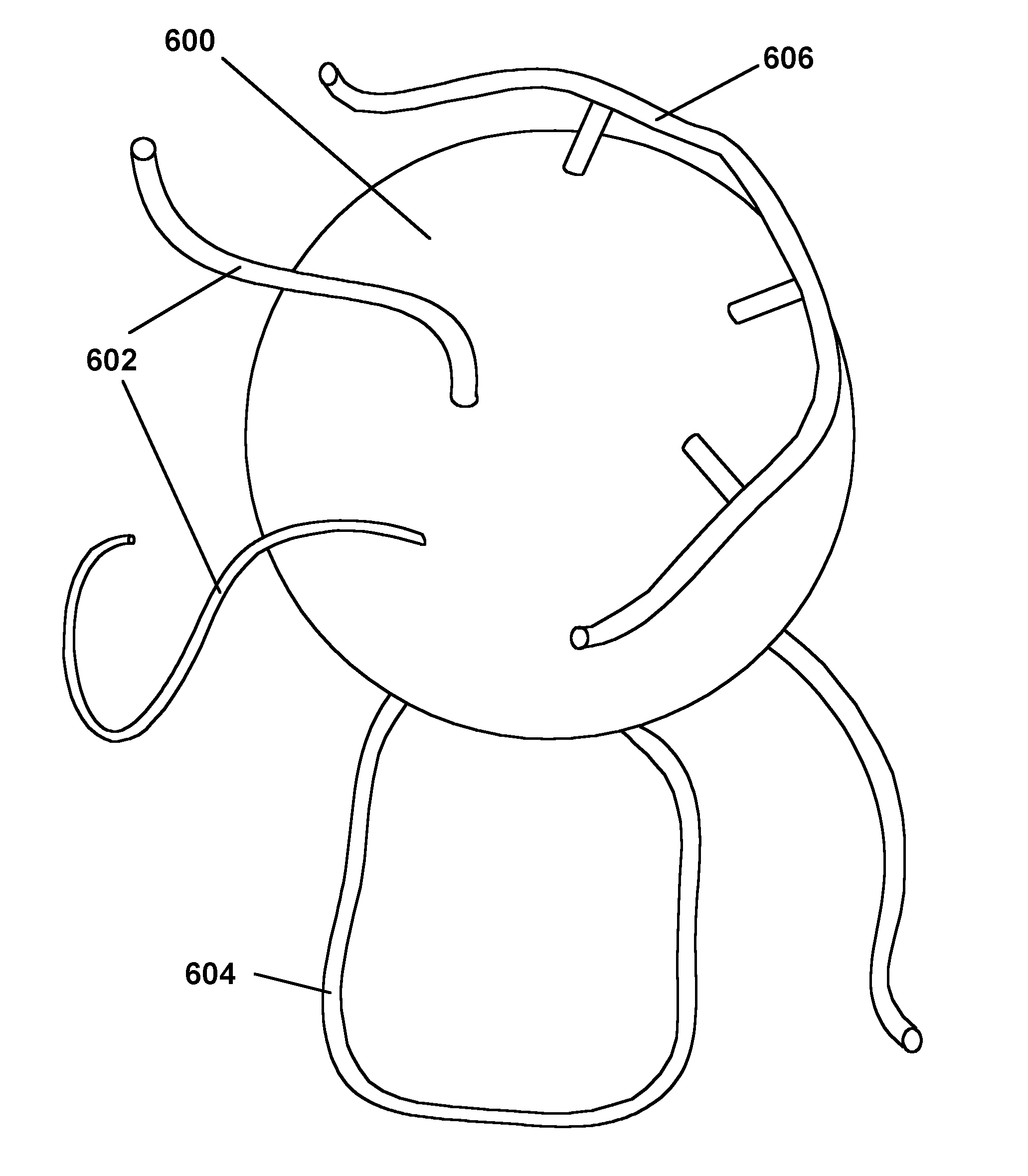
[0122] In a first process described in the aforementioned 2002 / 0185378 (hereinafter called the “random graft
polymerization” or “RGP” process), as illustrated in FIG. 5A, a particle 500 is reacted with a
reagent 502 having a functional group 504 capable of reacting with, and bonding to, the particle and with a polymerizable group, for example a pendant vinyl or other ethylenically unsaturated group 506. (The shapes used to indicate the functional group 504 and other functional groups discussed below are used only to make it easier to illustrate the reactions involved and, of course, bear no relationship to the actual physical shapes of the functional groups.) The functional group reacts 504 with the particle surface, leaving a residue indicated at 504′ attached to the particle and also leaving the polymerizable group 506 covalently bonded to the particle surface and free to participate in a subsequent
polymerization reaction; in effect, the entire treated particle 508 becomes a polymerizable “
monomer” (although in practice this
monomer is usually multifunctional, in the sense of containing a plurality of polymerizable groups). The particle 508 carrying the polymerizable group is then treated with one or more polymerizable monomers or oligomers under conditions effective to cause reaction between the polymerizable group 506 on the particles and the monomer(s) or
oligomer(s). If the polymerizable group on the particle is a radical-reactive olefinic group capable of
radical polymerization, such conditions will, of course, typically include the presence of a
radical polymerization initiator, although in some cases the polymerization may be initiated thermally, with no initiator present. As indicated at 510 in FIG. 5A, the
resultant polymerization reaction produces polymer chains which include at least one residue from a polymerizable group previously attached to the particle; if, as is usually the case, multiple polymerizable groups are attached to the particle in the first stage of the process, the residues of two or more of these polymerizable groups may be incorporated into the same polymer chain, which will thus be attached to the particle surface at two or more points.

