Method for producing composite ceramic material

a composite ceramic and manufacturing method technology, applied in the direction of packaging foodstuffs, physical/chemical process catalysts, impression caps, etc., can solve the problems of atopy, other diseases, atopy, and other diseases, and the appearance of buildings, and the deterioration of construction materials

Inactive Publication Date: 2005-08-11
NAT INST OF ADVANCED IND SCI & TECH
View PDF2 Cites 9 Cited by
  • Summary
  • Abstract
  • Description
  • Claims
  • Application Information

AI Technical Summary

Problems solved by technology

Aldehydes that evaporate from adhesives and the like contained in wallpaper and other construction materials, and ammonia and other chemical substances contained in tobacco smoke generally become causes of chemical hypersensitivity, atopy, and other maladies.
Soiling of buildings and other structures due to atmospheric contamination and other factors brought about by automobile exhaust and the like damages the appearance of the buildings and causes construction materials to deteriorate.
Exterior wall materials, automobiles, train cars, or other items that are used for long periods of time outdoors have particularly noticeable soiling by the atmosphere, marks from oils washed out by rain, and other types of contamination.
Marks from oily flows are particularly prominent under window frames and the like; for example, contamination is noticeable on the white tenting used in domed baseball stadiums and the like, and also on bullet trains and other train cars.
This contamination is made up of carbon and other atmospheric dust that is fixed by oils, and is not easily removed by cleaning with detergents.
However, an organic binder cannot be used, and the coating does not function in the absence of light, so almost no effects are obtained at night or in a darkened room.
An attempt has recently been made to use a visible light photocatalyst, but these visible light photocatalysts are also incapable of physical adsorption, so only substances that come in contact with the surface can be treated, and the effects remain inadequate even when these catalysts are applied to building materials.
Furthermore, visible light-reactive photocatalysts have enhanced activity in the visible light region but extremely poor reactivity to light in the ultraviolet region.
When an organic coating material is used as a component of a coating material, there are also drawbacks whereby the coating film deteriorates due to the organic coating material component coming into direct contact with TiO2 and the like.
Because of its strong photocatalytic activity, titanium dioxide has drawbacks in that the catalyst itself breaks down and causes discoloration, peeling, and crumbling when mixed with an organic binder and applied to paper or resin.
There has conventionally been no alternative but to perform a so-called double application whereby a coating material is formed using an inorganic binder, and the coating material containing the titanium dioxide powder is applied as a top coat or the like after an undercoat has been applied, which takes two or more days to complete and is impractical, particularly in roadside building or in soundproofing walls for expressways.
Such coating has only been possible on tile or other ceramic walls or metal.
Making a surface hydrophilic to prevent contamination using an organic coating material and other methods have been investigated, but adequate stain-proofing effects have so far been unobtainable.
In this method, however, artificial body fluid is used; it is impossible to create apatite in the desired shape, such as a rod shape or hexagonal column; and production time or productivity is inadequate.

Method used


Image

  • Method for producing composite ceramic material
  • Method for producing composite ceramic material
  • Method for producing composite ceramic material

Examples


example 1

(1) Manufacturing Method

Process (1)

[0061] 900 mg of CaCl2 were dissolved in 1 mL of water (solution 1).

[0062] 3 mL of 1 L of an aqueous solution containing 1450 mM of Na+, 42 mM of K+, 1410 mM of Cl−, 80 mM of HCO33−, and 95 mM of HPO4− were added to the solution 1 above (solution 2).

[0063] 1 g of TiO2 (anatase 15 nm) was added to this solution and stirred vigorously.

Process (2)

[0064] The solution to which water (50 mL) was immediately added was centrifuged for three minutes at 3000 rpm, and the supernatant was discarded.

[0065] The addition of water and the centrifugation were repeated to remove the ions in the fluid.

(2) Results

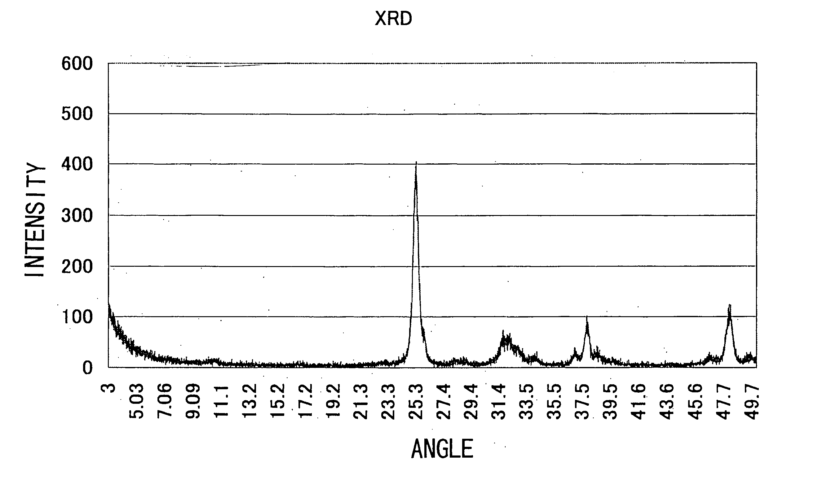
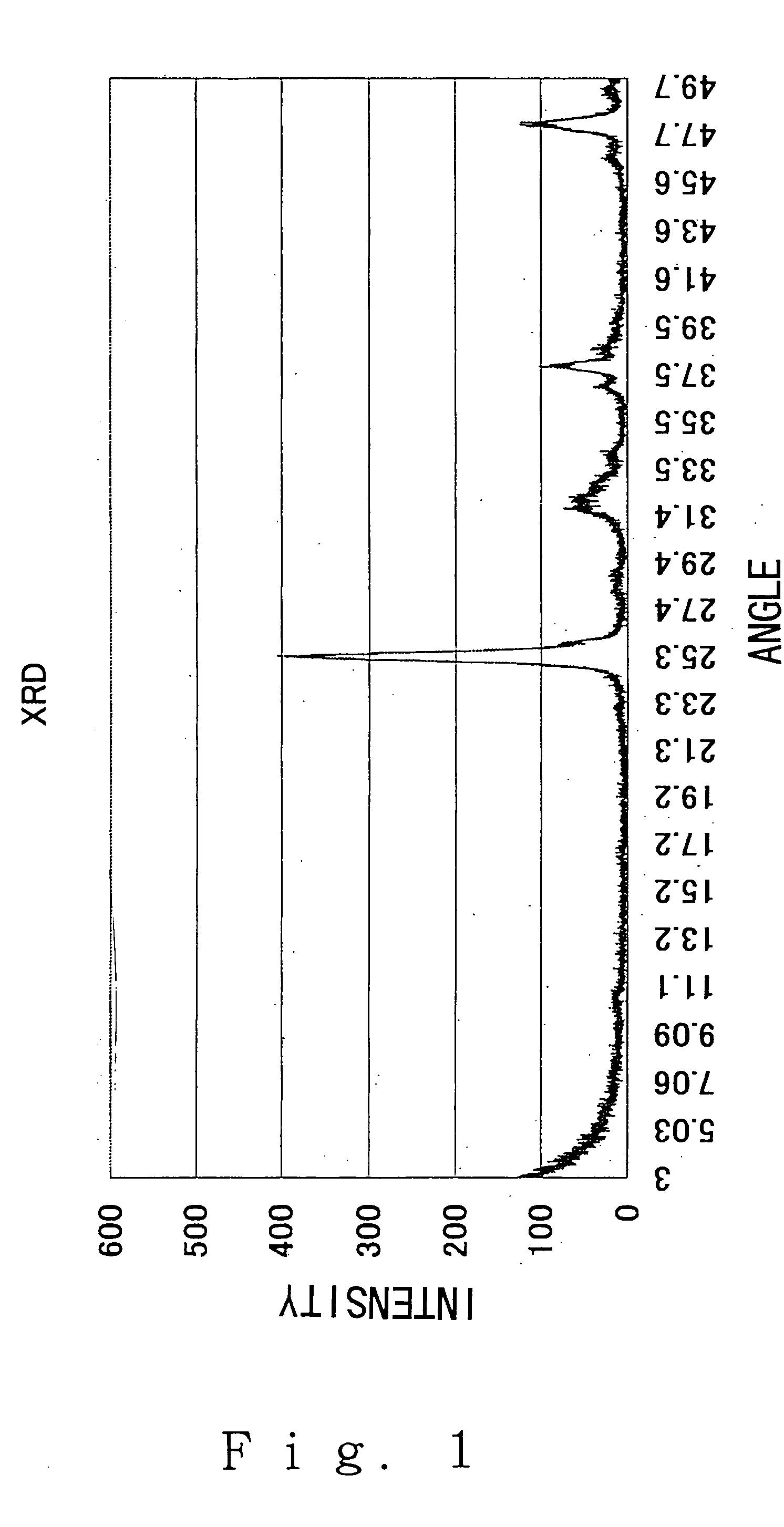
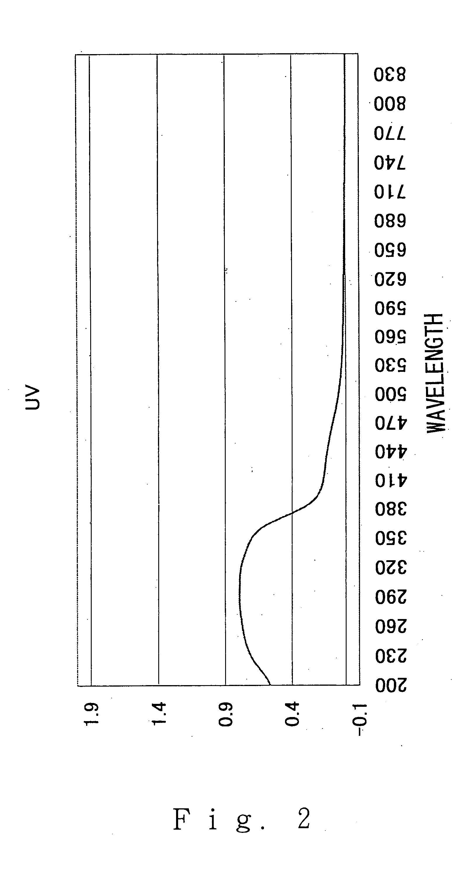
[0066]FIG. 1 shows the X-ray diffraction (after apatite precipitation) and FIG. 2 shows the UV to visible absorption spectrum (after apatite precipitation). FIG. 3 shows an electron micrograph. As is clear from these data, the precipitated crystal was apatite having a rod shape.

example 2

(1) Manufacturing Method

Process (1)

[0067] 60 mg of CaCl2 and 10 mg of zinc nitrate were dissolved in 1 mL of water (solution 1).

[0068] 3 mL of 1 L of an aqueous solution containing 42 mM of K+, 80 mM of HCO33−, and 95 mM of HPO4− were added to solution 1 above (solution 2).

[0069] 1 g of TiO2 (anatase 6 nm) was added to this solution and stirred vigorously.

Process (2)

[0070] The solution to which water (50 mL) was immediately added was centrifuged for three minutes at 3000 rpm, and the supernatant was discarded.

[0071] The addition of water and the centrifugation were repeated to remove the ions in the fluid.

[0072] The precipitated crystal was-apatite having a rod shape the same as in Example 1 above.

example 3

(1) Manufacturing Method

Process (1)

[0073] 1500 mg of CaCl2 were dissolved in 1 mL of water (solution 1).

[0074] 1 g of TiO2 (anatase 15 nm) was added to this solution and stirred vigorously.

[0075] 3 mL of 1 L of an aqueous solution containing 1450 mM of Na+, 42 mM of K+, 1410 mM of Cl−, 80 mM of HCO33−, and 95 mM of HPO4− were added to solution 1 above (solution 2)

Process (2)

[0076] The solution to which water (50 mL) was immediately added was centrifuged for three minutes at 3000 rpm, and the supernatant was discarded.

[0077] The addition of the water and the centrifugation were repeated to remove the ions in the fluid.

(2) Results

[0078] The precipitated crystal was apatite having a rod shape the same as in Example 1 above.


PUM

PropertyMeasurementUnit
specific surface areaaaaaaaaaaa
mean particle diameteraaaaaaaaaa
temperatureaaaaaaaaaa

Abstract

The present invention provides a method for manufacturing a titanium dioxide photocatalyst composite material, and relates to a method for manufacturing a titanium dioxide composite ceramic material on which photoactive (photooxidative) apatite or another calcium phosphate monocrystal is partially deposited, wherein the method is characterized in promoting the following reactions by immersing titanium dioxide in an aqueous solution containing an excess of phosphorus ions and calcium ions in comparison with an artificial body fluid in order to fabricate a titanium dioxide photocatalyst composite material on which a compound composed of one or more apatite or other calcium phosphate Ca9(PO4)6 monocrystals is partially deposited: (1) forming and aggregating calcium phosphate clusters and producing octacalcium phosphate; (2) converting the octacalcium phosphate into an apatite or other calcium phosphate Ca9(PO4)6 monocrystal; and (3) growing the monocrystal.

Description

TECHNICAL FIELD [0001] The present invention relates to a method for manufacturing a composite ceramic material, and more particularly relates to a method for manufacturing a titanium dioxide composite ceramic material provided with photoactivity (photooxidation ability) and high adsorption capacity and obtained by the partial deposition of apatite or another Ca9(PO4)6 calcium phosphate crystal. The present invention is useful in providing a method for producing a novel composite ceramic photocatalytic material whereby a large amount of processing can be performed in a short time compared to a conventional method that uses artificial body fluid. BACKGROUND ART [0002] Aldehydes that evaporate from adhesives and the like contained in wallpaper and other construction materials, and ammonia and other chemical substances contained in tobacco smoke generally become causes of chemical hypersensitivity, atopy, and other maladies. Soiling of buildings and other structures due to atmospheric ...

Claims


Application Information

Patent Timeline
Patent Type & Authority Applications(United States)
IPC IPC(8): B01J21/06B01J27/18B01J35/00
CPCB01J21/063B01J35/004B01J27/1806B01J27/18B01J35/02B82B3/00B82Y30/00
Inventor NONAMI, TORU
Owner NAT INST OF ADVANCED IND SCI & TECH
Why Eureka
Try Eureka