[0009] One object of the invention is to provide an attenuating filter for
ultraviolet light with wavelengths shorter than 200 nm that is capable of withstanding continuous-duty
laser irradiation. It is another object that the attenuating filter should be both simple and inexpensive to fabricate and capable of being antireflection coated, if necessary.
[0013] the filter coating including at least one layer fabricated from a dielectric material that absorbs over a predefined
wavelength range. This allows a variation of the
transmittance of the filter coating to be obtained by varying the thickness of the
dielectric layer.
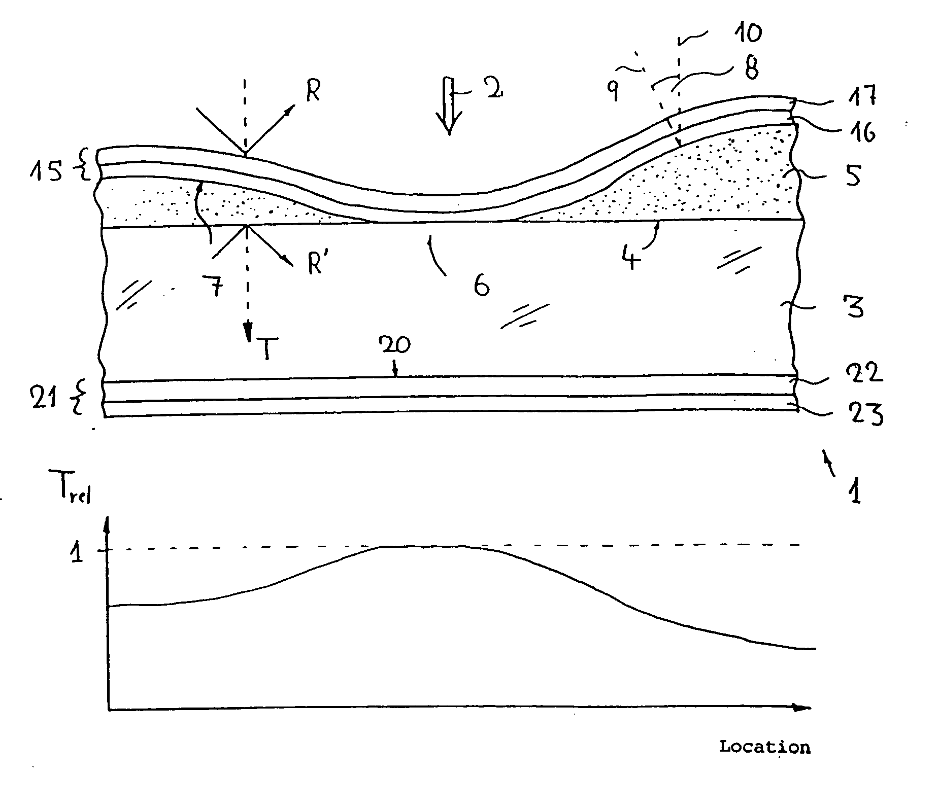
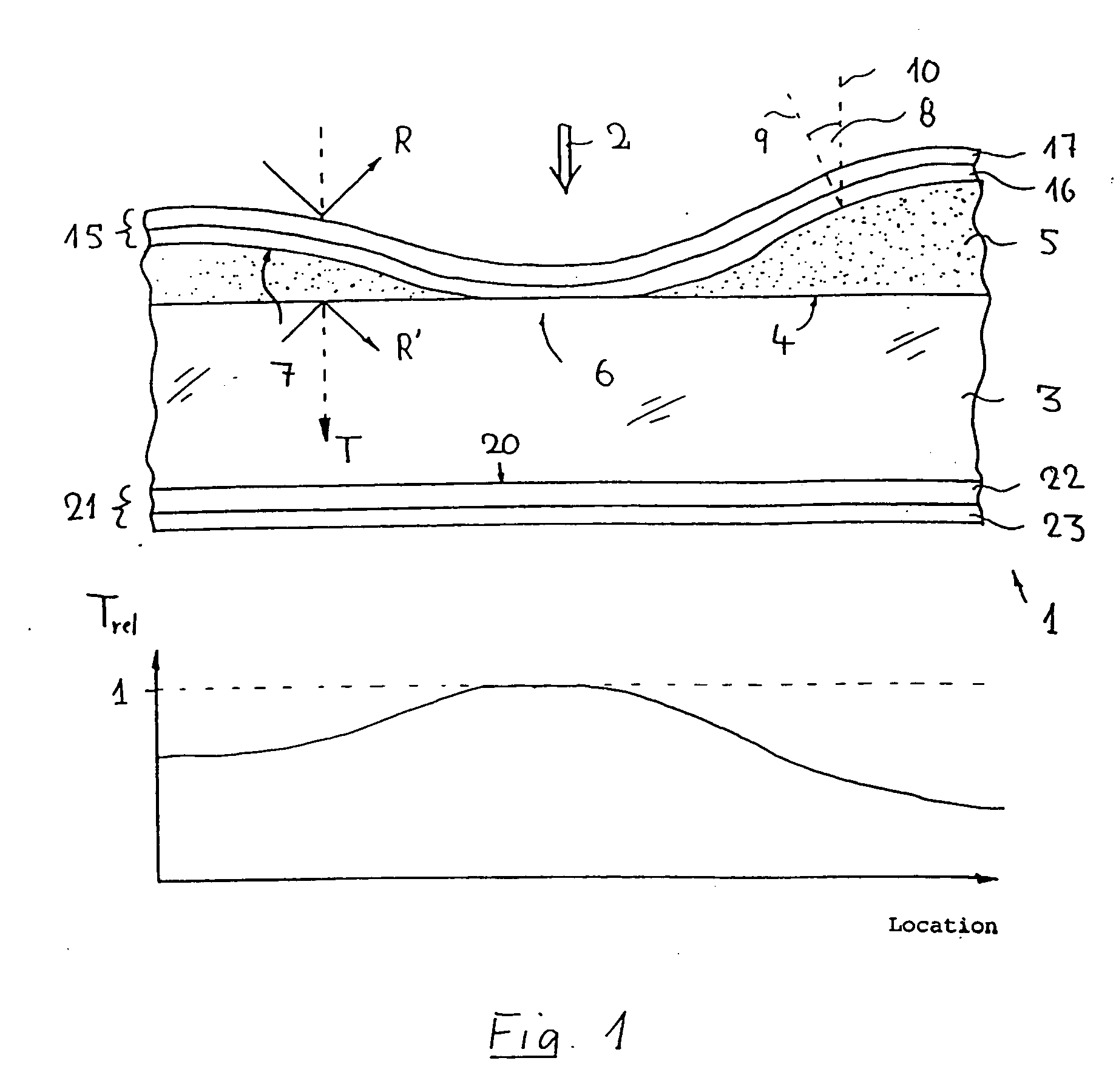
[0015] An attenuating filter in the sense of the invention that is of that type mentioned at the outset hereof is characterized in that its filter coating consists of at least one layer of a dielectric material that absorbs over that predefined
wavelength range to be involved, whereby a major share of its filtering effect will be due to absorption of
radiation within the filter coating. The absorbing dielectric material is to be chosen such that it has an effective cross-section at the prescribed operating wavelength that is large enough to ensure that a rapid variation in the
transmittance of the layer of dielectric material may be obtained by varying its thickness, if desired. On the other hand, any reductions in its transmittance due to reflection losses will be either low or negligible, which will be particularly highly beneficial in the case of applications that require avoiding
stray light and / or employment of filters with high total transmittances. A uniform attenuating effect over the entire filter surface may be obtained if a uniform thickness of the filter coating is applied.
[0018] Employment of
tantalum oxide or
tantalum pentoxide for fabricating optical filters, particularly interference filters, is, as such, known. However,
tantalum oxide, whether alone or admixed with other materials, has thus far largely been employed for fabricating antireflection coatings for the visible spectral region (cf., e.g., German Pat. Nos. DE 690 21 420 C2 or DE 30 09 533 C2).
Tantalum oxide is also frequently employed for fabricating coatings that have high transmittances in the visible and high reflectances in the
infrared (cf., e.g., German Pat. Nos. DE 38 25 671 and DE 692 08 712). However, in such applications, the absorption of
tantalum oxide is negligible.
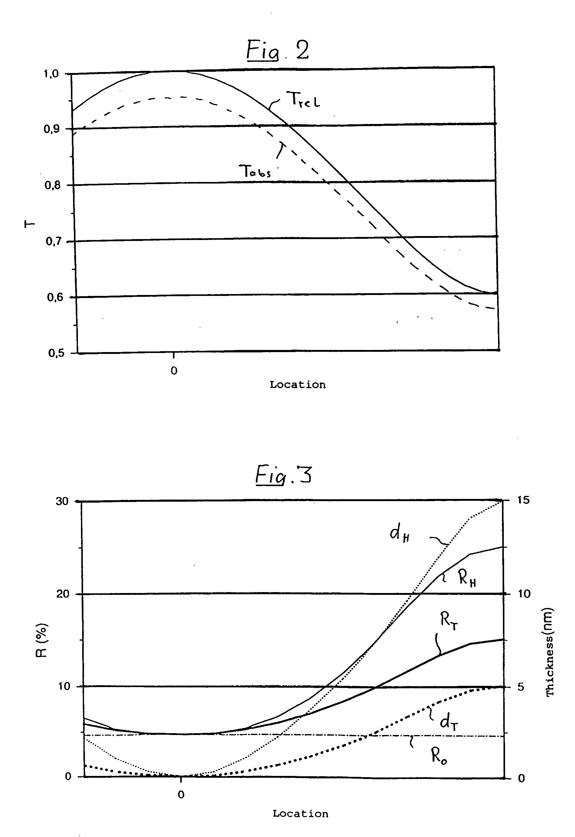
[0020] Filter coatings with low thicknesses of, e.g., around 1 nm to 2 nm, have another
advantage in that they may be effectively antireflection coated employing simply configured antireflection coatings. In particular, uniform antireflection coatings, i.e., antireflection coatings that have virtually constant, low, reflectances over the entire coated surfaces of filters to which they are applied, may be realized employing antireflection coatings with largely uniform thicknesses, since localized thickness gradients in the absorbing coatings involved will usually be so slight that they will have negligible effects on the local angles of incidence on the coated surfaces. The angles of incidence will thus roughly equal the angles of incidence on the substrates involved, which will usually be less than 20°. The angles of incidence on the coated surfaces and the substrates will thus be largely identical, even if the materials from which the respective filter coatings involved are fabricated have relatively low absorption coefficients, k. Effective
antireflection coating thus need not be either
broadband or effective over widely varying angles of incidence. The preferred, thin, filter coatings, may thus be effectively antireflection coated employing relatively simply configured antireflection coatings.
[0022] Several embodiments of the invention foresee application of an
antireflection coating to that face of the substrate of the attenuating filter opposite that to which the filter coating is applied, where the
antireflection coating may be either a single-layer or a multilayer coating. The
resultant virtual
elimination of reflection losses at both the entrance and exit faces of the attenuating filter will allow achieving the best possible (total) reductions of reflection losses, which will be of particular importance in the case of those attenuating filters for controlling illumination levels in the image planes of projection lenses mentioned at the outset hereof, since high illumination levels will allow achieving high
wafer through puts and thus cost-effective fabrication of semi-conductor devices.

