
Apparatus and method for selective processing of materials with radiant energy

a technology of radiant energy and apparatus, applied in the field of apparatus and method for selective processing of materials with radiant energy, can solve the problems of significant heat loss, reduced efficiency, and inefficient conversion of radiation generators, and achieve the effects of maximizing the contact volume of airflow, reducing heat loss, and increasing speed

Inactive Publication Date: 2005-09-08
DOUGLAS MACHINE LIABILITY
View PDF37 Cites 18 Cited by
  • Summary
  • Abstract
  • Description
  • Claims
  • Application Information

AI Technical Summary

Benefits of technology

[0054] The current industry standard for heating shrink film is to use hot air convection heating. Air has a low heat capacity thus requiring large volumes of hot air be passed across the film surface to convey enough energy into the film. Air is a good insulator. Of the volume of air passing over the shrink film, heat transfers only from the small fraction of air that is able to contact the film. The air that is fractions of an inch away from the film does not transfer heat into the film. This becomes a problem of airflow management to maximize the contact of the volume of airflow with the film.
[0055] Using very hot air can cause burn thru or darkening in some spots while other areas are not heated enough. This puts an upper limit on air temperature, thus requiring larger volumes of air to transfer the same quantity of heat. A high temperature may also overheat the outer surface of the film while the inner surface is cooler affecting the strength of the film.
[0056] Because of these limitations of air heating, it takes some time to transfer the required heat energy into the film to cause it to shrink.
[0057] Radiant heat energy travels at the speed of light. Radiant energy can be focused on the film at very high wattages. The rate of heating is not limited by the deficiencies of air. A high rate of heating requires much less time that increases the speed of shrinking.
[0058] Another principal object and advantage of the present invention is increased efficiency.
[0059] With air heat, the hot air continually heats other non-desirable surfaces. The air must be contained and continually recycled. This also heats the structure of the shrink tunnel. These structures are insulated, however they continually leak away energy into the surrounding environment. Since packages must enter the shrink tunnel, a significant amount of hot air escapes as each package enters and exits the shrink tunnel again adding to the heat losses.

Problems solved by technology

For each of these methods, there are benefits and drawbacks for various materials in various situations.
As long as the hot object is hot, there is a heat loss that reduces efficiency.
With air convection, there can be significant losses of heat as air escapes and products enter the vessel.
Some radiation generators are inefficient converters, only converting a small percentage of input energy into the desired output energy.
The rest of the energy may be in an undesirable form such as waste heat.
This may require a cooling system that lowers the overall efficiency.
Since airflow is very difficult to control in all situations, the accuracy of heating with air is also very difficult to control.
Since conduction requires physical contact, it can be extremely difficult to construct a mechanism to heat randomly located or moving items.
The fluid flow can be very difficult to predict and control.
This makes convection the least accurate for placement.
The primary obstacle to using radiation is the absorption spectrum of the target material not matching the spectrum of energy being generated.
A second obstacle is the added cost of a control system required to make this type of system perform well.
The control costs are primarily associated with the mechanisms needed for accuracy of heating and accuracy of placement.
In the packaging industry, aesthetics has become an increasingly important issue, both for the package that is produced and the machine that produces it.
Many of the challenges in producing aesthetically pleasing “bulls eyes” stem from the way that current heat tunnels operate using convection heating.
Current heat tunnels often produce deformed bulls eyes due to uncontrolled airflow.
That is, as the group of articles enclosed in shrink-wrap film enters the heat tunnel, the film is subjected to various disruptive air currents, causing the film to flutter as it is shrunk.
This uncontrolled airflow results in the film wrinkling and shrinking non-uniformly, which in turn results in unaesthetically pleasing bulls eyes.
Furthermore, current heat tunnels are not generally adjustable for various product sizes.
This causes undesirable effects of heating the products and surrounding structure, with a very small fraction of energy absorbed by the plastic.
Typical infrared lasers such as CO2 lasers also emit a broad spectrum of IR energy making them impractical for shrinking film.
It takes time to heat up causing delays before the first page can be printed.
This wastes electricity and requires a cooling fan to keep the printer from overheating while not in use.
When printing at high speed, the fusing roller may be the limiting factor due to its' limited heat transfer rate.
The power available from most AC power outlets becomes an upper limit to using more powerful fusing rollers in fast printers and copiers.
However, the UV light is directed indiscriminately at the page, rather than only to areas on the page where toner is present.
Another drawback with the water bath is the mess and inconvenience of getting the reaction vessels wet and the loading and unloading.
If one of the vessels leaks, the water bath could be contaminated.
Working with hot water can cause burns.
However, a long-standing problem has existed in the manufacture of bottles that do not have a circular cross-section.
With pre-forms that are to be made into bottles having rectangular or oval cross-sections, it is difficult to achieve uniform wall thickness.
If uniform wall thickness is not achieved, particularly in the base of the bottle, the base may have distortions that can cause the bottle to rest unevenly on a surface and even tip over.
However, they have not been very successful, particularly in the area of the pre-form closed end, because it has not been practical, because of the small size of the closed end, to heat profile sub-regions within the closed end.
However, not only does this require a special mold, but the resulting bottle has unusual rib-like grooves in its base.
Furthermore, the temperature profiling process used in the past, as illustrated by U.S. Pat. No. 6,514,448, has required very complex mechanical systems and a number of radiant heaters and coolers.
The more it stretches, the thinner it gets.
This process creates a problem of controlling the uniformity of the wall thickness.
The heat energy is difficult to accurately place using these methods.
These methods of heating the pre-form are difficult to adjust and get ‘dialed in’ for consistent wall thickness control.
This has the effect of blurring the desired heat profile.
Also with current designs, it is very difficult to control the heating of the base of the pre-form since it is a smaller region, and is positioned at the end.
The thick plastic does not cool as fast and can lead to distortions of the base when prematurely removed from the mold when running at higher speeds.

Method used


Image

  • Apparatus and method for selective processing of materials with radiant energy
  • Apparatus and method for selective processing of materials with radiant energy
  • Apparatus and method for selective processing of materials with radiant energy

Examples


Embodiment Construction

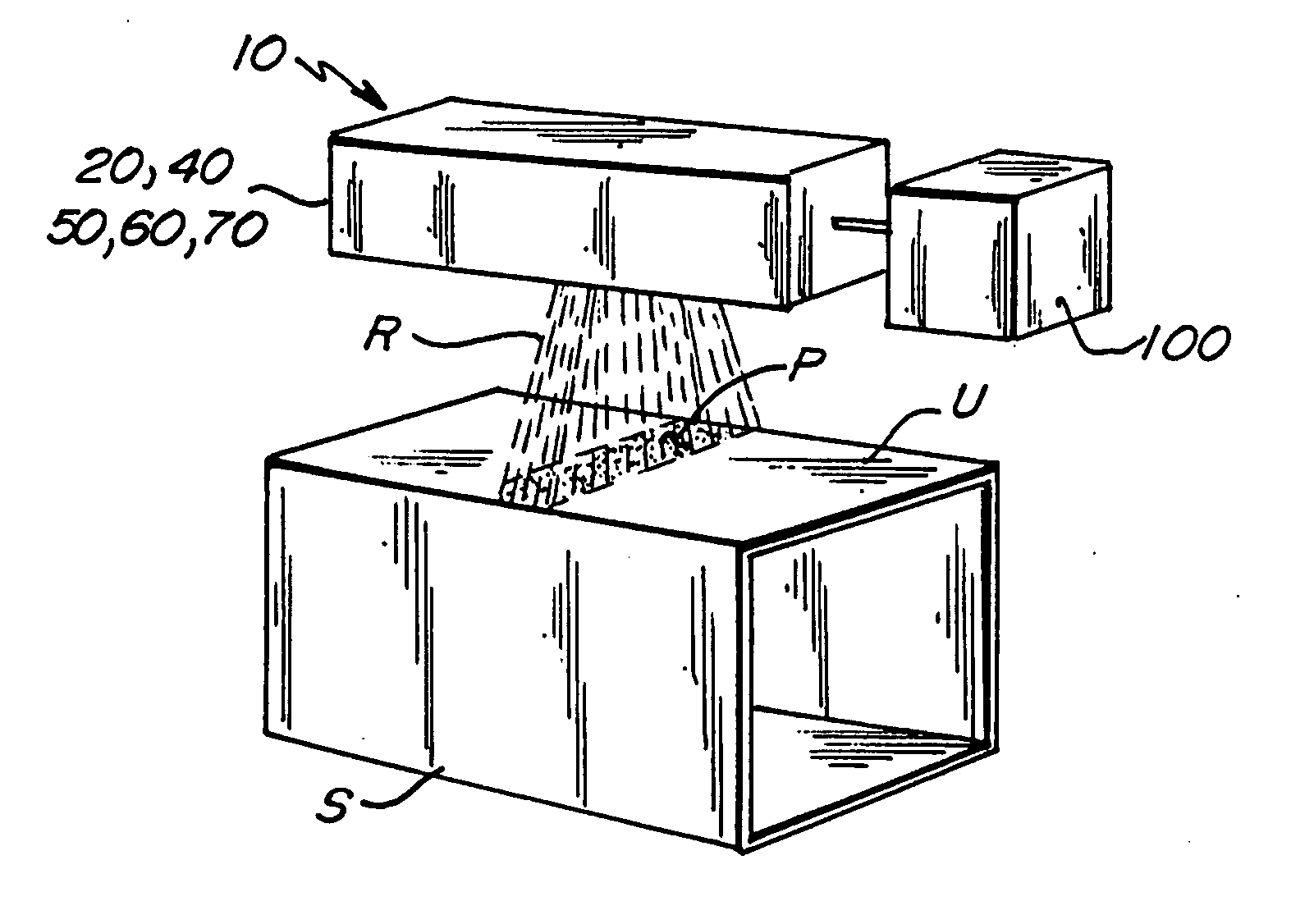
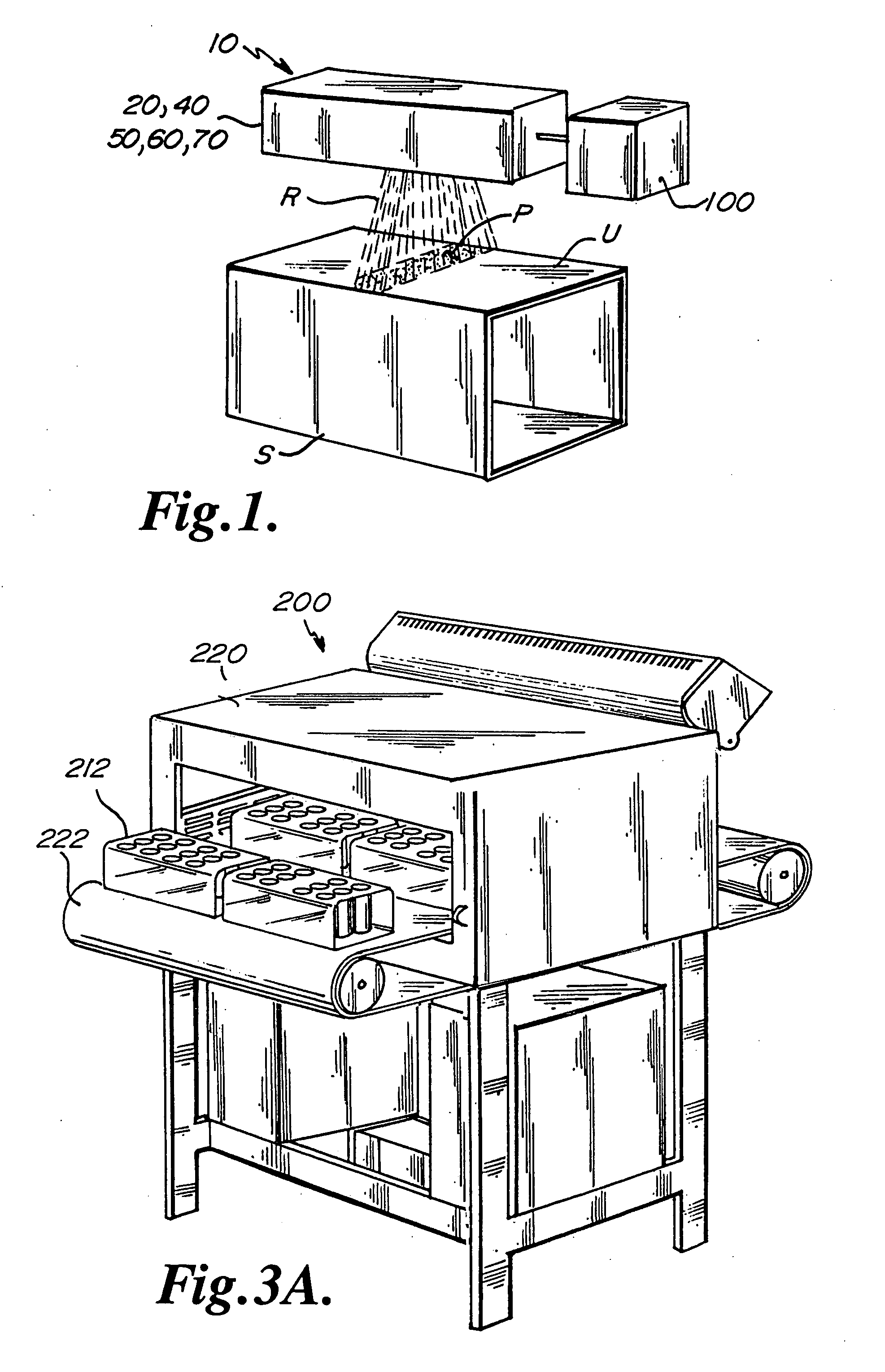
[0129] In general terms, as shown in FIG. 1, the present invention comprises an apparatus 10 for selective processing of a substrate S using radiant energy. The substrate S has a portion P to be processed and a larger portion U to be substantially unprocessed.

[0130] The apparatus 10 further comprises a source 20 of radiant energy R having a customizable wavelength λc or spectrum of wavelengths λc1, λc2, adapted to be configured to be specifically absorbed by the portion P to be processed and to substantially unabsorbed by the portion U.

[0131] In one embodiment, the source 20 of radiant energy R is a quantum cascade laser 40. Preferably, the quantum cascade laser 40 is configured to emit infrared radiation. Alternatively, the quantum cascade laser 40 is configured to emit visible radiation as a guide for alignment and verification of operation. Alternatively, the quantum cascade laser 40 may be configured to emit ultraviolet radiation.

[0132] The QC laser, invented at Bell Labs in ...


PUM

PropertyMeasurementUnit
wavelengthaaaaaaaaaa

Abstract

Apparatus for selective processing of a substrate using radiant energy. The substrate can consist of any target material having a portion to be processed using the radiant energy and a larger portion to be unprocessed. The apparatus consists of a source of radiant energy (preferably a quantum cascade laser) that has a customizable spectrum that can be configured to be specifically absorbed only by the portion to be processed, and a control system for targeting the radiant energy only at the portion to be processed. Specific examples of the use of the apparatus and method are in the technologies of heat-shrinking polyethylene film, fusing toner to paper in a laser printer, heating reaction vessels in DNA testing, and temperature profiling bottle pre-forms.

Description

[0001] The present application is a continuation-in-part of co-pending U.S. patent application Ser. No. 10 / 680,538, filed Oct. 7, 2003, titled “HEAT TUNNEL FOR FILM SHRINKING.”BACKGROUND OF THE INVENTION [0002] The present invention relates to an apparatus and method for processing materials using radiant energy. [0003] Many items are heated for processing operations. There are three main methods of heat transfer, namely conduction, convection, and radiation. For each of these methods, there are benefits and drawbacks for various materials in various situations. As a background, each of the heat transfer methods are rated on the following criteria: speed, efficiency, controllability of heat transfer rate, and controllability of spatial heat placement. In layman's terms, how fast is it heated, how cheaply is it heated, how accurately is it heated, and how well is the heat placed. The ideal heater is fast, cheap, accurate, and able to place heat accurately. [0004] Speed (Heat Transfer...

Claims


Application Information

Patent Timeline
Patent Type & Authority Applications(United States)
IPC IPC(8): B65B9/06B65B53/06
CPCB23K26/0036B29C66/83413B23K26/0648B23K26/0665B23K26/4065B29B13/024B29B13/025B29C33/26B29C49/04B29C49/06B29C49/6436B29C65/1606B29C65/1619B29C65/7473B29C66/1122B29C66/4312B29C66/71B29C66/73715B29C66/81267B29C66/849B29C2035/0822B29C2035/0838B29C2035/1658B29L2031/756B65B9/06B65B53/02B65B53/063B23K26/0639B29C65/1674B29C65/1629B29C65/1654B29C65/1664B29C65/1667B29K2023/06B23K26/0006B29C66/73921B23K26/064B23K2103/42B23K2103/50B29C2949/0715B29C2049/78675B29C2049/78805
Inventor SCHOENECK, RICHARD JEROME
Owner DOUGLAS MACHINE LIABILITY
Learn More