
Biosensor

a biosensor and sensor technology, applied in the field of biosensors, can solve the problems of deteriorating the performance of the sensor, difficult to keep the preservation container free of moisture penetration, and inability to completely eliminate the remaining water of molecular level in the biosensor reagent, etc., to achieve the effect of facilitating the formation of homogeneous reagents on the surface of electrodes, excellent stability and high respons

Inactive Publication Date: 2005-09-08
PHC HLDG CORP
View PDF13 Cites 16 Cited by
  • Summary
  • Abstract
  • Description
  • Claims
  • Application Information

AI Technical Summary

Benefits of technology

The present invention provides a biosensor that can accurately measure the concentration of a specific substance in a sample solution without being affected by other substances or contaminants. The biosensor includes a reagent layer with a specific sugar alcohol that helps to dissolve the specific substance in the sample solution and react with it. The biosensor also includes metallic salt that helps to prevent unwanted reactions and increase in background electric current with time. The biosensor is suitable for various examinations and can provide high-performance results with small variations among individual sensors.

Problems solved by technology

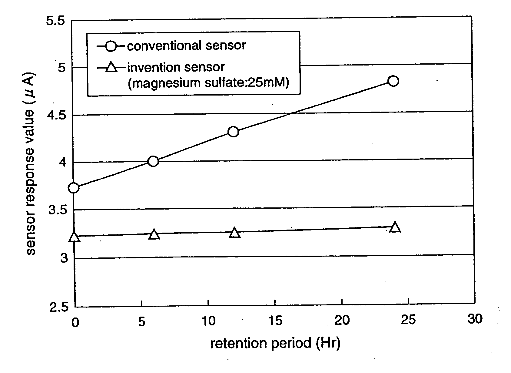
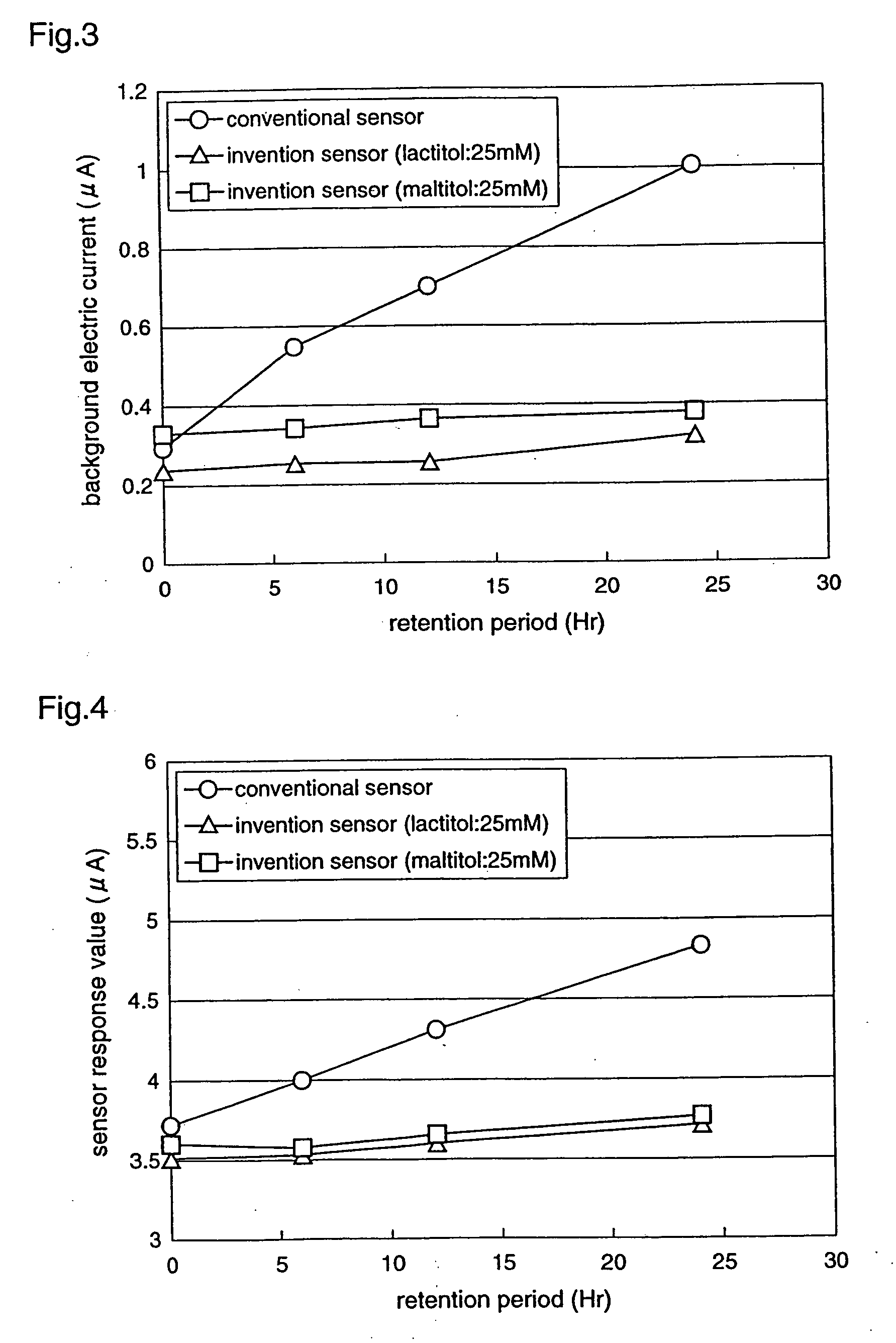
As the value of the background electric current increases with time, the sensor performance is deteriorated.
However, it is impossible to completely eliminate water of molecular level remaining in the reagent included in the biosensor, with the desiccant alone.
Further, it is extremely hard to keep the preservation container free of moisture penetration over long term, and the reduction reaction between a portion of enzyme protein or hydrophilic polymer and the electron transfer agent is promoted when only a slight amount of moisture exists.
Therefore, it is extremely difficult to effectively suppress the increase in the background electric current with time.
Further, when an inorganic salt such as potassium ferricyanide is included in the mixed reagent layer composed of various reagents such as an enzyme and an electron transfer agent, the reagent layer is extremely easily crystallized in the process of drying the reagent solution, whereby the surface of the reagent layer becomes rough and uneven, resulting in deterioration in the response (linearity, sensitivity) of the sensor to the substrate concentration and the measurement accuracy.

Method used


Image

  • Biosensor
  • Biosensor
  • Biosensor

Examples


embodiment 1

[0048] Hereinafter, a biosensor according to a first embodiment of the present invention will be described. In the respective embodiments of the invention described below, an enzyme sensor, which employs an enzyme as a molecular recognition element that specifically reacts to a specific substance in a sample solution, is exemplified.

[0049]FIG. 11 exemplifies an exploded perspective view of a three-electrode-system biosensor, and FIG. 12 exemplifies an exploded perspective view of a two-electrode-system biosensor. In FIGS. 11 and 12, numeral 1 or 101 denotes an insulating support, on which a working electrode 2 or 102 and a counter electrode 3 or 103 are formed at prescribed positions in prescribed shapes. Further, in the three-electrode-system biosensor shown in FIG. 11, a detecting electrode 4 is formed on the insulating support 1 at a prescribed position in a prescribed shape. The detecting electrode 4 here serves as an electrode for detecting shortage of a specimen quantity and,...

embodiment 2

[0067] Hereinafter, a biosensor according to a second embodiment of the present invention will be described.

[0068] The biosensor according to the second embodiment of the invention is the biosensor shown in FIG. 11 or 12 whose reagent layer 5 or 105 is formed of an enzyme, an electron transfer agent, a hydrophilic polymer, and a metallic salt. Other constituents are the same as those of the above-described biosensor according to the first embodiment and, therefore, descriptions thereof will be omitted.

[0069] The second embodiment of the invention is characterized by that a metallic salt is included in the reagent layer 5 or 105, and the metallic salt prevents that the oxidized-form electron transfer agent gets contact with a part of a reactive functional group existing in enzyme protein and hydrophilic polymer included in the reagent, so that the electron transfer agent is denatured (reduced) from the oxidized form to reduced form in the reagent layer 5 or 105 formed on the electr...

embodiment 3

[0074] Hereinafter, a biosensor according to a third embodiment of the present invention will be described.

[0075] The biosensor according to the third embodiment of the invention has a reagent layer 5 or 105 shown in FIG. 11 or 12, which is formed of an enzyme, an electron transfer agent, a hydrophilic polymer, and an organic acid or organic acid salt which has at least one carboxyl group in a molecule. Other constituents are the same as those of the above-described biosensor according to the first embodiment and, therefore, descriptions thereof will be omitted.

[0076] The third embodiment of the invention is characterized by that an organic acid or organic acid salt having at least one carboxyl group in a molecule is included in the reagent layer 5 or 105, and the organic acid or organic acid salt prevents that the oxidized-form electron transfer agent gets contact with a part of a reactive functional group existing in enzyme protein and hydrophilic polymer included in the reagent...


PUM

PropertyMeasurementUnit
humidityaaaaaaaaaa
temperatureaaaaaaaaaa
thickaaaaaaaaaa

Abstract

In a biosensor for measuring a specific substance in a liquid sample, one or a combination of sugar alcohol, metallic salt, organic acid or organic acid salt which has at least one carboxyl group in a molecule, and organic acid or organic acid salt which has at least one carboxyl group and one amino group in a molecule, is included in a reagent layer provided on electrodes, thereby providing a highly-accurate biosensor which is excellent in stability and has high response (sensitivity, linearity) of the sensor to the substrate concentration.

Description

TECHNICAL FIELD [0001] The present invention relates to a biosensor for analyzing a specific component in a liquid sample and, more particularly, to a reagent formulation for composing a reagent layer of the biosensor. BACKGROUND ART [0002] A biosensor is a sensor which utilizes the molecule identifying abilities of organic materials such as microorganisms, enzymes, and antibodies, and applies the organic materials as molecular recognition elements. That is, the biosensor utilizes a reaction which occurs when an immobilized organic material recognizes a target specific substance, such as oxygen consumption by respiration of a microorganism, an enzyme reaction, and luminescence. [0003] Among biosensors, enzyme sensors have been put to practical use. For example, enzyme sensors for glucose, lactic acid, cholesterol, lactose, urea, and amino acid are utilized in medical measurement or food industry. An enzyme sensor reduces an electron acceptor by an electron generated by a reaction be...

Claims


Application Information

Patent Timeline
Patent Type & Authority Applications(United States)
IPC IPC(8): C12Q1/00
CPCC12Q1/003
Inventor MIYAZAKI, SHOJITOKUNAGA, HIROYUKIFUJIWARA, MASAKINAKAMINAMI, TAKAHIRONAKAYAMA, JUNKOYAMANISHI, ERIKO
Owner PHC HLDG CORP
Learn More