Simple high efficiency optical coherence domain reflectometer design

a reflectometer and high-efficiency technology, applied in the field of optical imaging, can solve the problems of polarization fading, affecting the quality of the resulting image, and the configuration is limited to an optical efficiency of 25%, so as to reduce the cost of the ocdr system, the effect of reducing the cost of the system and being easy to conver

Active Publication Date: 2005-09-29
CARL ZEISS MEDITEC INC
View PDF13 Cites 195 Cited by
  • Summary
  • Abstract
  • Description
  • Claims
  • Application Information

AI Technical Summary

Benefits of technology

[0032] A further object of the invention is to use non-PM fiber and non-PM fiber pigtailed fiber optic devices so that the cost of the system is much lower than PM fiber based counterparts.
[0033] Another object of the present invention is to make it possible to adjust the polarization direction of the light wave projecting onto the sample without causing polarization fading resulting from the birefringence changes in the sample arm.
[0034] Another object of the present invention is to make it possible to achieve optical path length delay or phase modulation using a fiber-wrapped PZT based transmissive optical delay line in the lead non-PM fiber portion of either the reference arm or the sample arm, without causing polarization fading resulting from the birefringence changes in the fiber portion of the reference or sample arm.
[0035] Another object of the present invention is to also provide a configuration (embodiment 2) that can be easily converted between a two-detector-based balanced heterodyne detection scheme and a one detector based unbalanced detection scheme.
[0036] Still another object of the invention is to further lower the cost of an OCDR system by using a thin film base analyzer to achieve the one detector based unbalanced detection scheme in embodiment 2.

Problems solved by technology

However, this configuration is limited to an optical efficiency of 25% as explained below.
Another issue with the classic Michelson interferometer (FIG. 1) is that light from the reference arm is coupled back into the optical source, causing side effects that can impact the quality of the resulting image.
An issue not addressed by Izatt and Rollins configurations above is polarization fading, or loss of signal associated with mismatches between the polarization states of the light from the reference and sample arms.
Although this design solved the problem of polarization fading, it did not address the issue of optical efficiency as the optical splitter configuration is the same as the standard Michelson interferometer configuration of FIG. 1.
This leads to an unbalanced optical efficiency assuming no birefringence in the sample and the use of a polarized source.
A drawback of such a system is the additional cost of the Faraday rotator and furthermore, while polarization compensation is provided for the sample arm, the same is not provided for the reference arm and as a result, there will be a mismatch in the birefringence as well as the dispersion properties between the two arms.
Obviously, any birefringence fluctuation in the reference arm will still cause polarization fading and at the same time, the final output optical polarization of the configuration is not predetermined and hence is not suitable for spectral domain OCT which is polarization dependent.
PM fibers have several issues associated with their two orthogonal polarization axes, which make them undesirable for commercial OCDR or OCT applications.
These include variable optical dispersion, difficulties in maintaining high polarization extinction in the connection between two PM-fibers or between a PM-fiber and a polarization optical component, and high cost.
The problem with this approach is that the polarizer needs to be adjusted as the birefringence in the reference arm changes.
As the birefringence in the non-PM reference arm fiber is strongly affected by temperature and stress, the system must be recalibrated with each use, and suffers from polarization drift during use.
As the two arms use different types of optical fibers, their dispersion properties are drastically different, which hence will lead to loss of resolution due to mismatched dispersion between the sample and reference arms.
However, a major disadvantage of the disclosed designs is that the system configuration is not simple at all, as it involves length matched PM fiber and non-PM fiber between the sample and references arms, their splices or connections and the use of a relatively large number of various optical components such as (PM or non-PM) fiber coupler, free space polarization beam splitter (PBS), various Faraday rotators of different rotation angles, and two photodetectors.
All of these make the system both quite complicated and also expensive.

Method used


Image

  • Simple high efficiency optical coherence domain reflectometer design
  • Simple high efficiency optical coherence domain reflectometer design
  • Simple high efficiency optical coherence domain reflectometer design

Examples


embodiment 1

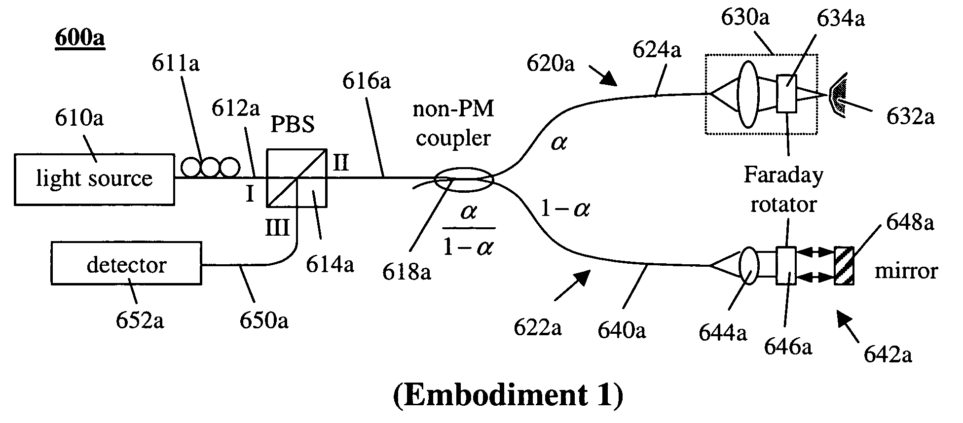
[0051]FIG. 6A is a diagram of the OCDR system according to a first embodiment of the present invention. The light source 610a introduces to the system 600a a linearly polarized light wave either through a linearly polarized light source 610a or by placing a linear polarizer (not shown) directly after an unpolarized source, wherein the linear polarizer can be an independent polarizer or the polarizing beam splitter as will be made clear below. The light source 610a has a center wavelength within the optical spectrum range from ultra-through violet to near infrared. It is preferably derived from a superluminescent diode (SLD), a light emitting diode (LED), a short pulsed laser such as a Ti:sapphire laser, a photonic crystal fiber laser or a spontaneous emission based rare earth doped optical fiber broad band light source. For these applications, the latter light sources are considered “low coherence” light sources. The subject invention can also be implemented with a frequency swept l...

embodiment 2

[0077]FIG. 7A is a diagram of the OCDR system according to a second embodiment of the present invention. The light source 710a introduces to the system 700a a linear polarized light wave either through a linearly polarized light source 710a or by placing a linear polarizer (not shown) directly after an unpolarized source. The light source 710a has a center wavelength within the optical spectrum range from ultra-violet to near infrared. It is preferably derived from a superluminescent diode (SLD), a light emitting diode (LED), a frequency swept laser, a short pulsed laser such as a Ti:sapphire laser, a photonic crystal fiber laser or a spontaneous emission based rare earth doped optical fiber broad band light source. The light source 710a is coupled through a short length of a non-PM fiber 712a to the input port (port I) of a polarizing / polarization beam splitter (PBS) 714a. Assuming that the PBS has two polarization modes or directions that are in the vertical and horizontal directi...


PUM

PropertyMeasurementUnit
optical rotation angleaaaaaaaaaa
optical coherence domain reflectometryaaaaaaaaaa
optical efficiencyaaaaaaaaaa

Abstract

The present invention discloses simple and yet highly efficient configurations of optical coherence domain reflectometry systems. The combined use of a polarizing beam splitter with one or two polarization manipulator(s) that rotate the returned light wave polarization to an orthogonal direction, enables one to achieve high optical power delivery efficiency as well as fixed or predetermined output polarization state of the interfering light waves reaching a detector or detector array, which is especially beneficial for spectral domain optical coherence tomography. In addition, the system can be made insensitive to polarization fading resulting from the birefringence change in the sample and reference arms. Dispersion matching can also be easily achieved between the sample and the reference arm for high resolution longitudinal scanning.

Description

BACKGROUND OF THE INVENTION [0001] 1. Field of the invention [0002] The invention relates generally to optical imaging and in particular to systems and methods for achieving flexibility in interference fringe visibility control and optimization of signal to noise ratio, as well as for achieving polarization insensitivity, dispersion matching and optical output polarization control in optical coherence domain reflectometry (OCDR) or optical coherence tomography (OCT). [0003] 2. Description of Related Art [0004] Optical coherence domain reflectometry (OCDR) is a technique initially developed to provide a higher resolution over optical time domain reflectometry (OTDR) for the characterization of the position and the magnitude of reflection sites in such optical assemblies as optical fiber based systems, miniature optical components and integrated optics (Youngquist et al., “Optical Coherence-Domain Reflectometry: A New Optical Evaluation Technique”, 1987, Optics Letters 12(3):158-160)....

Claims


Application Information

Patent Timeline
Patent Type & Authority Applications(United States)
IPC IPC(8): A61B5/00G01B9/02G01M11/00G01N21/47
CPCA61B5/0066A61B5/0084G01M11/3181G01N21/4795G01B2290/40G01B9/02044G01B9/02091G01B2290/70G01B9/0201
Inventor EVERETT, MATTHEW J.ZHOU, YAN
Owner CARL ZEISS MEDITEC INC
Why Eureka
Try Eureka