Electrolytic cell

a technology of electrolysis and cells, applied in the field of electrolysis cells, can solve the problems of inefficient processes, unsatisfactory problems, and long time-consuming treatment of waste water containing microorganisms, and achieve the effects of increasing turbulence, reducing turbulence, and high flow rate of water stream entering the cell

Inactive Publication Date: 2005-10-13
VEOLIA WATER TECH DEUT GMBH
View PDF9 Cites 20 Cited by
  • Summary
  • Abstract
  • Description
  • Claims
  • Application Information

AI Technical Summary

Benefits of technology

[0046] Preferably, the linear flow rate of the water stream entering the cell is so high that turbulence is easily achieved when reaching the first electrode. An increased turbulence results in increased mass transfer which in turn yields a more efficient treatment of the microorganisms. Preferably, the Reynold's number in the cell is higher than about 2000, and most preferably higher than about 5000. However, Reynold's number is preferably lower than about 100000.
[0047] Turbulence and thereby also mass transfer may be increased by increasing the flow of water.
[0048] The electrolysis taking place in the cell results in production of hydroxyl radicals and hydrogen peroxide which can kill microorganisms in order to prevent biofouling and other unwanted effects of microorganisms. The cell can also be useful in reducing COD in contaminated waters.
[0049] The hydroxyl radicals can be generated directly on the anode surface by oxidation of water on a suitable anode as defined herein. The hydroxyl radicals and other types of radicals m

Problems solved by technology

Treatment of waste water containing microorganisms has been performed for a fairly long period of time.
However, treatment processes based on electrolysis have hitherto not been completely problem-free.
Inefficient processes as well as expensive equipment or high energy consumption have previously prevented improved handling of microorganisms occurring in e.g. waste water, cooling water, ballast water, and recirculated washing water.
However, this process is very expensive and inefficient for applications where large volumes of water are treated due to extensive pressure drop, low flow rates, and low current efficiency.
This has, however, not always been seen to be a successful way of performing the chemical reactions in the cell.
This configuration, however, often results in pressure drops and lower throughput of the medium to be cleaned.
The retention time may also be prolonged which is not always satisfying, particularly if large volumes of contaminated water needs rapid treatment.

Method used


Image

  • Electrolytic cell
  • Electrolytic cell

Examples


example 1

[0062] Surface sea water containing plankton, coliform, and heterotrophic bacteria having a conductivity of 5 S / m was pumped into a tank of 800 litres and at the same time filtered through a cotton cloth and a 20 μm filter. Reference organisms of Tetraselmis and Isochrysis (both flagellates) were added together with a non-patogenic colony of the coliform E-choli bacteria. Control samples were taken.

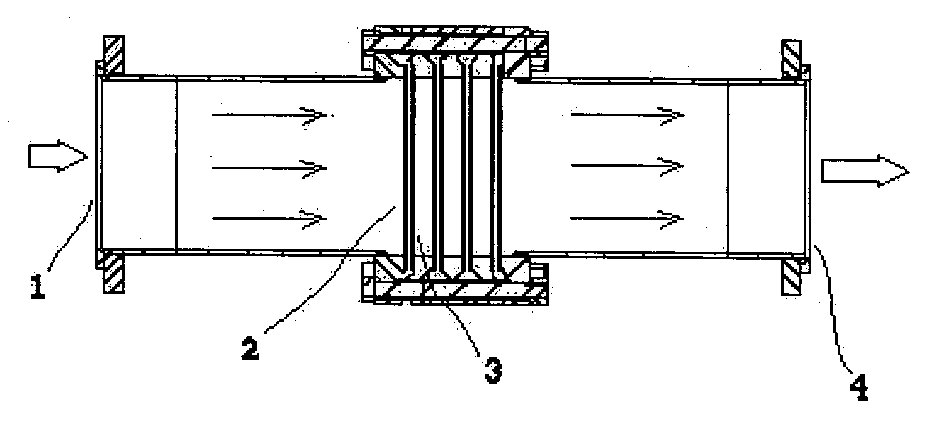
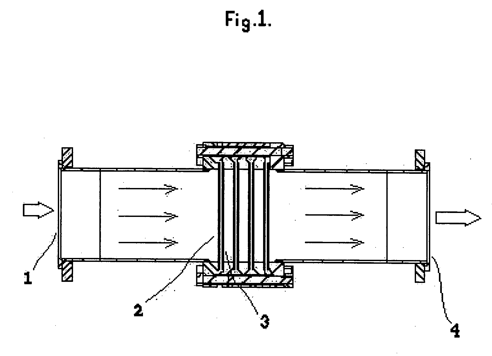
[0063] Both the anodes and cathodes used were expanded niobium plates coated with conductive boron-doped diamond (BDD). The electrochemical cell comprised six of these BDD electrodes arranged for crossflow passage of the natural sea water in a titanium tube having an inner diameter of 70 mm. The anodes and cathodes were arranged in pairs with a small space of 4 mm between anode and cathode of the same pair and a distance of 41 mm between adjacent pairs.

[0064] The water treated in the electrochemical cell was fed through the cell at a flowrate of 10 m3 / h (175 l / min) and a current density...

example 2

[0065] Natural surface sea water (from the west coast of Sweden) was prefiltered using a net and pumped into a tank of 800 litres. Control samples were taken.

[0066] The electrodes and the cell were the same as in example 1. The water was run at the same flow rate and current density, current and power were as in example 1. The treatment resulted in 84% killing of natural occurring zoo planktons and a 93% killing of naturally occurring phytoplanktons. Analysis was made by light microscopy. No THM formation occurred.

example 3 (

Reference)

[0067] An electrolytic cell as used in Example 1 but with a porous separator in between the anode and the cathode was prepared. 0.5 mm thick woven mesh with 30% opening made of polypropylene was used as the separator. The water to be treated was flown from the cathode to anode. The electrolysis examination was performed under same conditions as in example 1 but the flow rate could not attain a flow rate of 10 m3 / h but was only up to 3 m3 / h. Same electric current as example 1 was used. Several ppm of THM (tri-halo-methane) was shown to be formed in the sea water.


PUM

PropertyMeasurementUnit
Electrical conductivityaaaaaaaaaa
Flow rateaaaaaaaaaa
Fractionaaaaaaaaaa

Abstract

The present invention relates to a process of treating contaminated water containing microorganisms comprising feeding a contaminated water stream at a volumetric flow of about 1 to about 1000 m3 / h through an electrolyser zone, said water stream having a conductivity from about 0.0001 to about 100 S / m, electrolysing said water stream in said electrolyser zone defined by at least one electrode pair enabling treatment of microorganisms, said at least one electrode pair comprising an anode and a cathode without separator means, said water stream being guided substantially perpendicularly through said at least one anode and cathode while imposing a voltage across said anode and cathode and supplying a direct current to said anode and cathode, withdrawing from the electrolyser zone a treated water stream. The invention also relates to an electrolytic cell in which said process can be performed, and to the use of the electrolytic cell.

Description

[0001] The present invention relates to a process of treating contaminated water comprising microorganisms, an electrolytic cell in which the process is carried out, and the use of the cell for treatment of contaminated waters derived from various applications and sources. BACKGROUND OF THE INVENTION [0002] Treatment of waste water containing microorganisms has been performed for a fairly long period of time. However, treatment processes based on electrolysis have hitherto not been completely problem-free. Inefficient processes as well as expensive equipment or high energy consumption have previously prevented improved handling of microorganisms occurring in e.g. waste water, cooling water, ballast water, and recirculated washing water. U.S. Pat. No. 5,419,824 discloses an electrolytic cell for destroying contaminants. However, this process is very expensive and inefficient for applications where large volumes of water are treated due to extensive pressure drop, low flow rates, and ...

Claims


Application Information

Patent Timeline
IPC IPC(8): C02F1/00C02F1/461C02F1/467
CPCC02F1/4672C02F2001/46157C02F2103/008C02F2103/023C02F2103/42C02F2301/024C02F2303/04
Inventor NYMAN, LARSHERLITZ, FREDRIKECHARDT, JONASSHIMAMUNE, TAKAYUKIHAKANSSON, HELGA
Owner VEOLIA WATER TECH DEUT GMBH
Why Eureka
Try Eureka