

Polarizing plate and production process of the same
a technology of polarizing plate and production process, which is applied in the direction of polarizing element, adhesive process, surface pretreatment, etc., can solve the problems of shrinkage of color unevenness or color deletion, difficult laminate of protective film formed of alicyclic structure-containing polymer, and difficult laminate of protective film on polarize, etc. problems, to achieve the effect of reducing color unevenness and color deletion with time, excellent adhesiveness, and stably producing polarizer
- Summary
- Abstract
- Description
- Claims
- Application Information
AI Technical Summary
Benefits of technology
Problems solved by technology
Method used
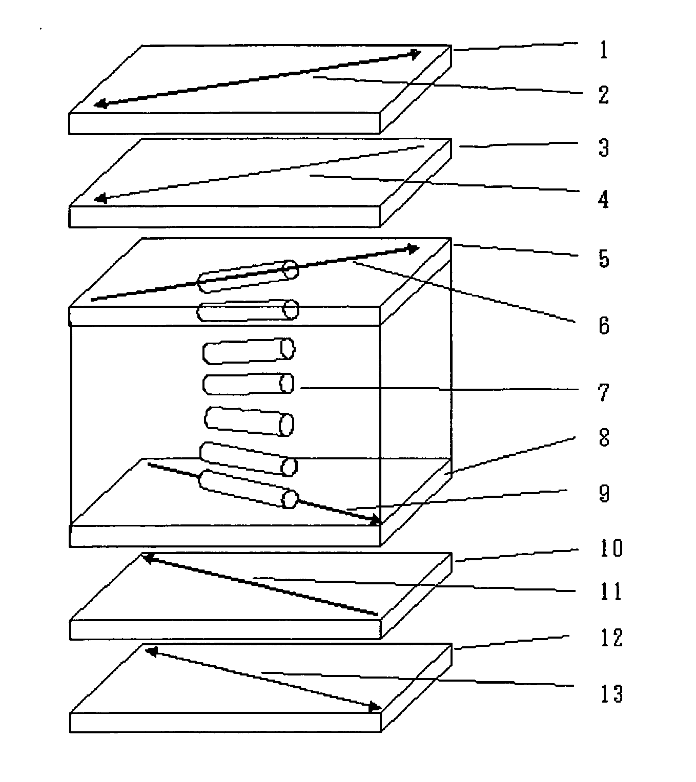
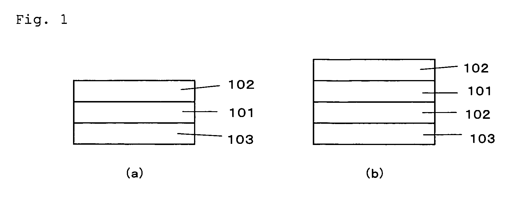
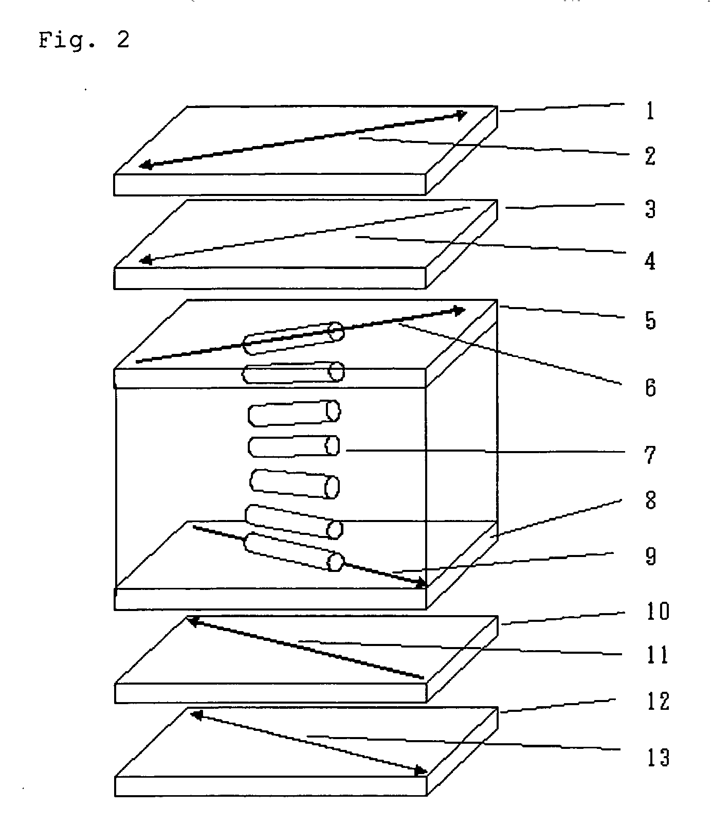
Image

Examples
example 1
Preparation of Polarizing Plate A
Example 1-1
Preparation of Polarizer
[0199] An aqueous solution prepared by dissolving a PVA powder having an average degree of polymerization of 2,400 and a degree of hydrolysis of 99.9% or more in pure water so as to have a concentration of 12% by weight was coated on a polyester film, dried at 40° C. for 3 hours, and further dried at 110° C. for 60 minutes, thereby obtaining a PVA film having a thickness of 75 μm The resulting film was swollen by warm water at 30° C. for one minute and dipped in an aqueous solution of potassium iodide / iodine (weight ratio: 10 / 1) at 30° C. and uniaxially stretched two times in the longitudinal direction. The concentration of the aqueous solution of potassium iodide / iodine (weight ratio: 10 / 1) was adjusted such that the iodine concentration was 0.38% by weight. Subsequently, the film was uniaxially stretched in the longitudinal direction in a total stretch ratio of 7 times in a 4.25% boric acid aqueous solution at ...
example 1-2
Protective Film
[Production of Raw Material for Protective Film]
[0201] In a reactor, 0.75 parts of 1-hexene, 0.18 parts of dibutyl ether and 0.46 parts of triisobutylaluminum were added to and mixed with 480 parts of dehydrated cyclohexane under a nitrogen atmosphere, to which were then continuously added for polymerization a norbornene based monomer mixture consisting of 78 parts of tricycle[4.3.0.12,5]deca-3,7-diene (dicyclopenta-diene, hereinafter abbreviated as “DCP”), 52 parts of 1,4-metano-1,4,4a,9a-tetrahydrofluorene (hereinafter abbreviated as “MTF”) and 68 parts of tetracyclo[4.4.0.12,5.17,10]-dodeca-3-ene (hereinafter abbreviated as “TCD”) and 41 parts of tungsten hexachloride (a 0.8% toluene solution) over 3 hours while keeping at 44° C. To the polymerization solution, 1.0 part of butyl glycidyl ether and 0.48 parts of isopropyl alcohol were added to inactivate the polymerization catalyst, thereby stopping the polymerization reaction.
[0202] Subsequently, 300 parts of cy...
example 2
Preparation of Polarizing Plate B
[0209] A polarizing plate B was prepared in the same manner as in Example 1-1, except that ZEONOR NF16 (manufactured by ZEON Corporation, which is a film having a film thickness of 100 μm and made of a saturated alicyclic structure-containing thermoplastic resin) was used as the protective film and that the surface treatment was performed by a flame treatment at a combustion amount of 300 kcal / cmh for 0.1 seconds using a flame treatment device manufactured by Chugai Ro Co., Ltd. The contact angle of the surface of the protective film having been subjected to a surface treatment in this Example against pure water was 37°.
[0210] Also, the polarizing plate B had a single plate transmittance of 43.2%, a degree of polarization of 99.96% and at nsnittance at410 nm of 0.16%.
PUM
| Property | Measurement | Unit |
|---|---|---|
| contact angle | aaaaa | aaaaa |
| transmittance | aaaaa | aaaaa |
| surface free energy | aaaaa | aaaaa |
Abstract
Description
Claims
Application Information