Manufacturing process using microwave for thermal debinding

a manufacturing process and microwave technology, applied in the direction of coatings, etc., can solve the problems of increasing processing costs, increasing time and energy for pre-heating and heat maintenance, and consuming considerable amounts of energy, so as to accelerate production procedures, reduce production costs, and rapid drying

Inactive Publication Date: 2005-11-10
FAR EAST COLLEGE
View PDF11 Cites 25 Cited by
  • Summary
  • Abstract
  • Description
  • Claims
  • Application Information

AI Technical Summary

Benefits of technology

[0020] The primary object of the invention is to provide a manufacturing process capable of accelerating production procedure, reducing production cost, rapidly drying and removing adhesives, fillings or lubricants. The manufacturing process is suitable for debinding of cast bodies after powder materials are mixed with adhesives, fillings or lubricants, and is able to avoid energy wastage in heating and temperature lowering as well as keeping away from being bulky in size.

Problems solved by technology

However, the cast additives used come as high as 30 vol %, and defects incurred are prone to arise during removal of the polymer materials in the debinding process.
However, such means of solvent debinding brings forth environmental and recycling issues and thus further increases processing expenses thereof.
Nevertheless, it is necessary to pre-heat the furnaces to a temperature required for thermal debinding, meaning that time and energy for pre-heating and energy consumed during maintaining the heat yet sum up to considerable amounts of money, and an efficiency problem often abstained by the manufacturing process is resulted.
Also, defects are prone to occur during the time-consuming thermal debinding process, and hence reforms with respect to the above shortcomings can yet be advanced.
It shall be taken into consideration that a chemical solvent, which is non-eco-friendly and is limited to a certain number of times to be used, is adopted for solvent debinding; and furnaces employed for thermal debinding are quite energy consuming.
The furnaces are troublesome and time-consuming in lowering the temperatures thereof.
During heating of a common furnace, a major part of energy is absorbed through the furnace body and lost into the atmosphere, and thus leaving as little as 30 percent of the original energy for debinding the body.
It is indeed uneconomical to waste such great amounts of energy for merely achieving the purpose of debinding.
Common furnaces take up large spaces for that they are massive in volume and heavy in weight, and lack mobility so that difficulties arise when moving such furnaces.
Furnaces have high equipment cost.
Expense burdens and maintenance fees thereof are unnecessarily increased.
Also, problems of heating bodies and heat-resistant materials are easily caused by any contamination of adhesion decompositions in the furnaces.
Besides, expired chemical solvents may become another environmental dilemma.
Defects are liable due to uneven temperature distribution in conventional heating.
Not only temperature inside a furnace but also temperature in and out of the sample is unevenly distributed.
As a result, defects such as breakage, deformation, swelling and collapsing are produced in the thermal debinding process.
Therefore, the shortcomings of the aforesaid debinding means (solvent debinding and thermal debinding) are yet not resolved by the Taiwan Patent Publication No. 167524.
Conclusive from the above, as described by shortcomings and issues of the conventional debinding means, the handling of the solvent used in solvent debinding are troublesome, uneconomical and non-eco-friendly, and furnaces adopted for thermal debinding are time-consuming for heating and temperature lowering.

Method used


Image

  • Manufacturing process using microwave for thermal debinding
  • Manufacturing process using microwave for thermal debinding
  • Manufacturing process using microwave for thermal debinding

Examples


Embodiment Construction

[0028] To better understand the manufacturing process and functions of the present invention, descriptions shall be given with the accompanying drawings below.

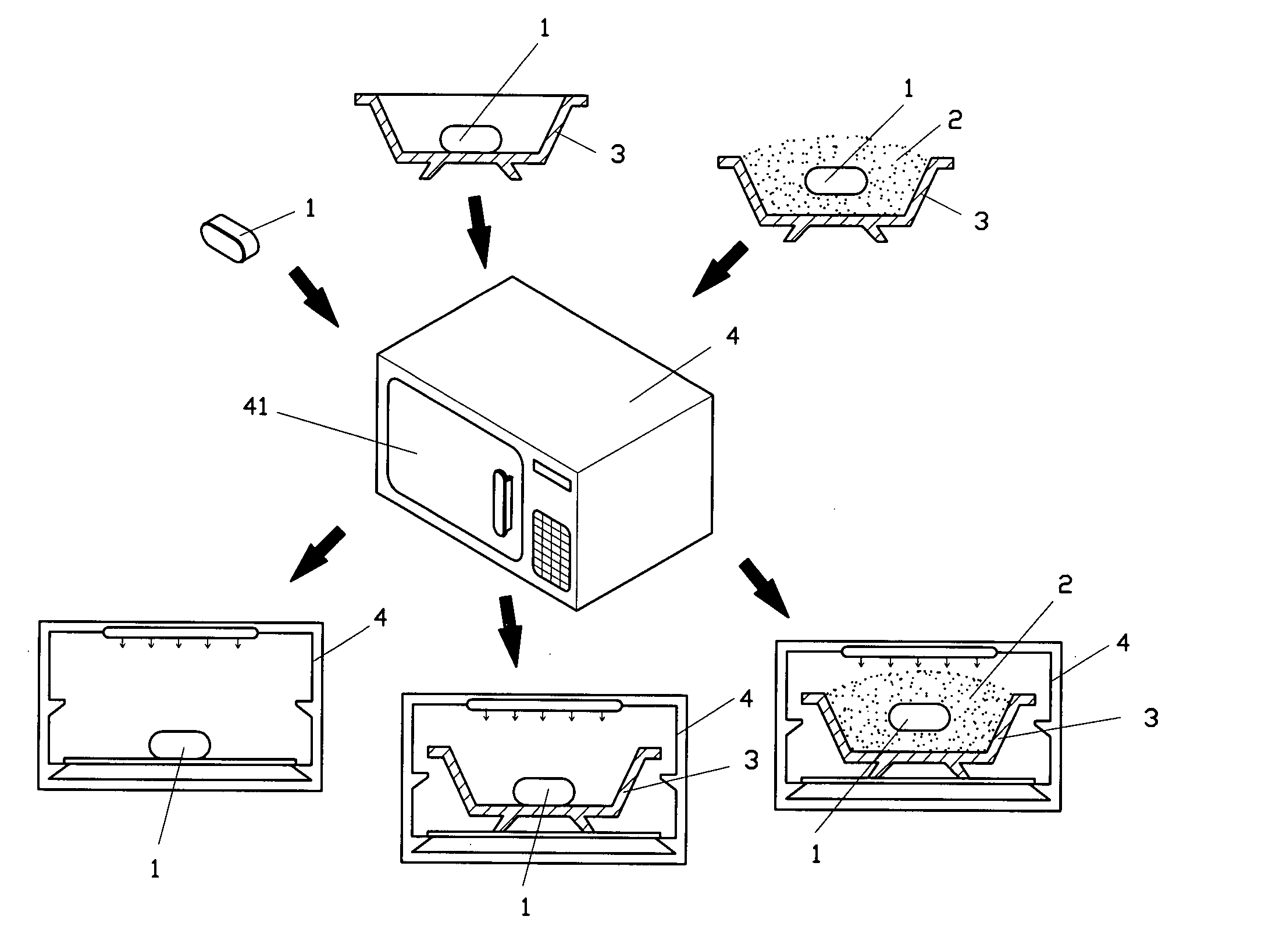
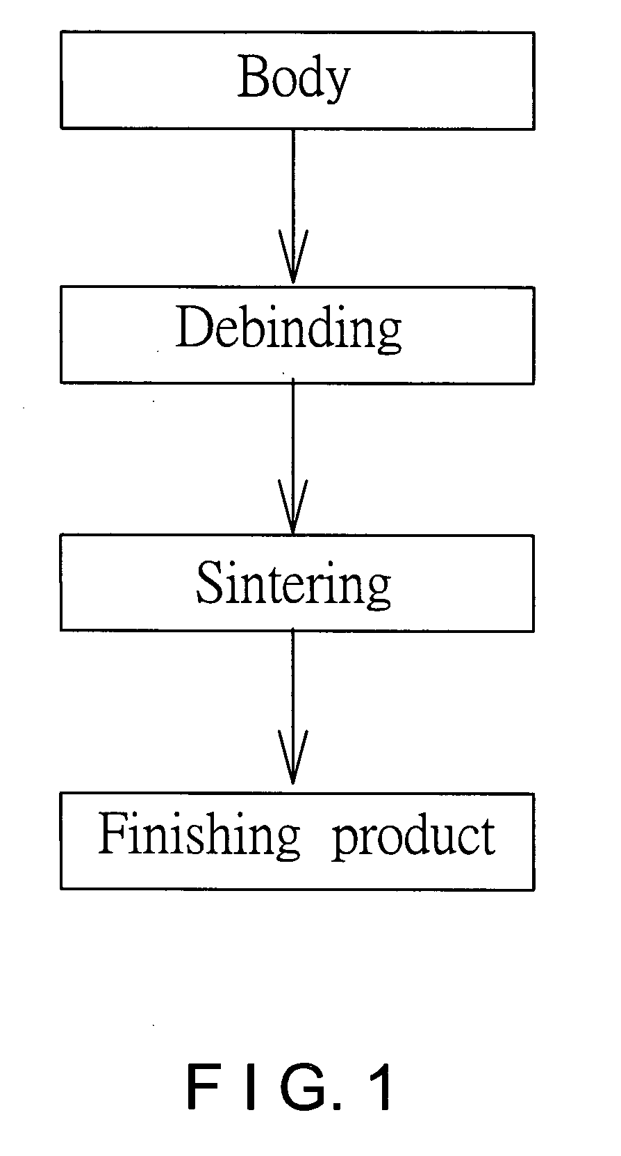
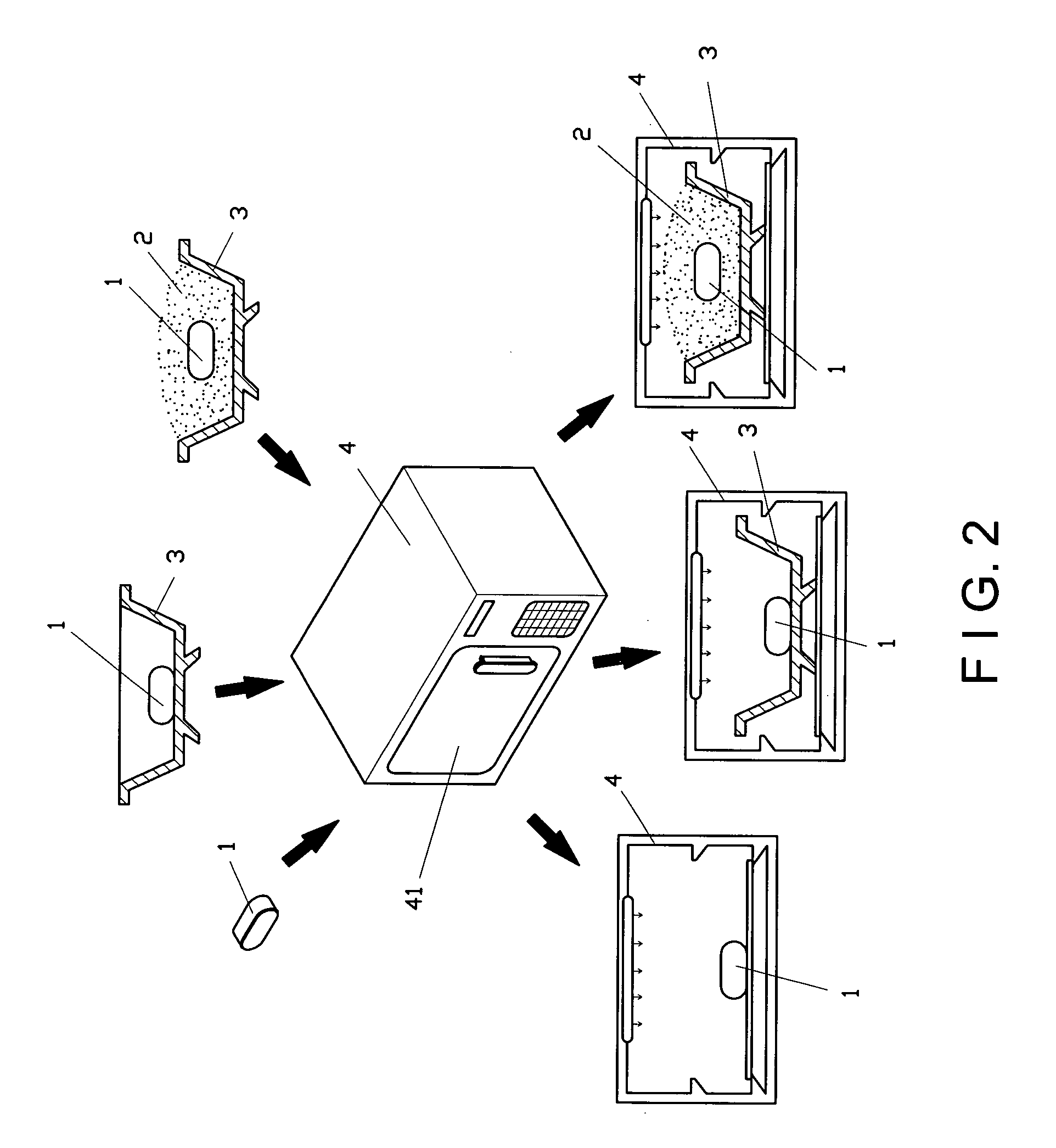
[0029] Referring to FIG. 1, procedures of powder metallurgy are: a. forming a body, b. debinding, c. sintering, and d. finishing product. The invention is a manufacturing process using microwave for thermal debinding. When being applied in powder metallurgy, the invention comprises the steps of: [0030] a. forming a body: powder of iron, nickel and copper is mixed with a weight ratio of 90:6:4, and the mixture is then blended with a mixture of low density polyethylene (LDPE), ethylene vinyl acetate (EVA), paraffin wax (PW) and stearic acid (SA) with a weight ratio of 12:12:61:15 at a temperature range between 120 to 160° C. for forming a body 1; wherein the aforesaid metal may be pure metals or alloys of iron (Fe), titanium (Ti), copper (Cu), magnesium (Mg), nickel (Ni), chromium (Cr) and manganese (Mn); [0031] b. debinding: t...


PUM

PropertyMeasurementUnit
temperatureaaaaaaaaaa
poweraaaaaaaaaa
reaction timeaaaaaaaaaa

Abstract

A manufacturing process using microwave for thermal debinding according to the invention is mainly applied in manufacturing process of powder metallurgy. Wherein, metal powder is mixed polymer materials such as adhesives, fillings or lubricants, and a body is formed by means of molding, forging, extrusion, injection or scraping. The body to be debinded is placed in a microwave environment in an exposed manner or covered with powder, and power and work time of microwave are set for rapidly heating and debinding the body. The manufacturing process according to the invention is capable of accelerating manufacturing procedure, economizing production cost, reducing defects, quickly drying and rapidly removing polymer materials.

Description

BACKGROUND OF THE INVENTION [0001] (a) Field of the Invention [0002] The invention relates to a manufacturing process using microwave for thermal debinding, and more particularly, to a manufacturing process using microwave for thermal debinding applied in powder metallurgy. Appropriate microwave power and reaction time are utilized for heating and rapidly debinding a body, thereby minimizing defects of finished products of powder metallurgy, economizing equipment and resource costs, quickly drying and rapidly removing polymer materials namely adhesives, fillings and lubricants. [0003] (b) Description of the Prior Art [0004] In common manufacturing processes of powder metallurgy, in order to facilitate ceramic powder to cast into bodies more easily, polymer materials are frequently added to the bodies as cast additives. Such type of cast additives includes adhesives, surfactants, fillings or lubricants. The cast additives are mixed with polymer materials for casting bodies that may b...

Claims


Application Information

Patent Timeline
Patent Type & Authority Applications(United States)
IPC IPC(8): B22F3/10
CPCB22F3/1025B22F2999/00B22F2003/1054
Inventor WANG, JENN-SHINGLIN, WEN-HAOCHEN, CHIH-CHENG
Owner FAR EAST COLLEGE
Why Eureka
Try Eureka