Photobioreactor and process for biomass production and mitigation of pollutants in flue gases

a photobioreactor and biomass technology, applied in the field of photobioreactors, can solve the problems of inability to achieve the rate-limiting step in the aqueous phase, and inability to achieve commercially successful results

Inactive Publication Date: 2005-11-24
GREENFUEL TECHNOLOGIES CORPORATION
View PDF72 Cites 243 Cited by
  • Summary
  • Abstract
  • Description
  • Claims
  • Application Information

AI Technical Summary

Benefits of technology

[0018] In yet another embodiment, a photobioreactor apparatus comprising at least a first, a second, and a third fluidically interconnected conduits, at least one of which is at least partially transparent to light of a wavelength capable of driving photosynthesis, the conduits together providing a flow loop enabling a liquid medium contained within the photobioreactor to flow sequentially from a region of origin within the flow loop through the first, second, and third conduits and back to the region of origin, the first, second, and third conduits being constructed and arranged so that at least one of the conduits forms an angle, with respect to the horizontal, that differs from an angle formed with respect to the horizontal of at least one of the other conduits, and wherein at least one of the conduits forms an angle, with respect to the horizontal, of greater than 10 degrees and less than 90 degrees is disclosed.
[0019] In another embodiment, a photobioreactor system comprising a photobioreactor comprising a least a first and a second fluidically interconnected conduits containing a liquid medium therein, at least one of which conduits is at least partially transparent to light of a wavelength capable of driving photosynthesis, a first gas sparger configured and positioned to introduce a gas stream into the first conduit, a second gas sparger configured and positioned to introduce a gas stream into the second conduit, and at least one outlet configured to release gas from the photobioreactor; and a controller configured to control the overall flow rate of a gas to be treated by the photobioreactor and the distribution of the overall flow rate to the first and second gas spargers so as to induce a liquid flow in the first conduit having a direction that is counter-current to a direction of flow of gas bubbles in the first conduit and so as to induce a liquid flow in the second conduit having a direction that is co-current to a direction of flow of gas bubbles in the second conduit is disclosed.

Problems solved by technology

In addition, algae are capable of growing in saline waters that are unsuitable for agriculture.
Although photosynthesis is fundamental to the conversion of solar radiation into stored biomass, efficiencies can be limited by the limited wavelength range of light energy capable of driving photosynthesis (400-700 nm, which is only about half of the total solar energy).
The dissolution of NO in the aqueous phase is believed to be the rate-limiting step in this NOX removal process.
Each program took a different approach but because of various problems, addressed by certain embodiments of the present invention, none has been commercially successful to date.
A major obstacle for feasible algal bio-regeneration and pollution abatement has been an efficient, yet cost-effective, growth system.
The ponds require low capital input; however, algae grown in open and uncontrolled environments result in low algal productivity.
The open pond technology made growing and harvesting the algae prohibitively expensive, since massive amounts of dilute algal waters required very large agitators, pumps and centrifuges.
Furthermore, with low algal productivity and large flatland requirements, this approach could, in the best-case scenario, be applicable to only 1% of U.S. power plants.
On the other hand, the MITI approach, with stricter land constraints, focused on very expensive closed algal photobioreactors utilizing fiber optics for light transmission.
In these controlled environments, much higher algal productivity was achieved, but the algal growth rates were not high enough to offset the capital costs of the expensive systems utilized.
These bioreactors, when oriented horizontally, typically require additional energy to provide mixing (e.g., pumps), thus adding significant capital and operational expense.
Photobioreactors that do not utilize solar energy but instead rely solely on artificial light sources can require enormous energy input.
Since no precisely defined flow lines are reproducibly formed, it can be difficult to control the mixing properties of the system which can lead to low mass transfer coefficients poor photomodulation, and low productivity.
However, control over the flow patterns within an air lift reactor to achieve a desired level of mixing and photomodulator can still be difficult or impractical.
In addition, because of geometric design constraints, during large-scale, outdoor algal production, both types of cylindrical-photobioreactors can suffer from low productivity, due to factors related to light reflection and auto-shading effects (in which one column is shading the other).

Method used


Image

  • Photobioreactor and process for biomass production and mitigation of pollutants in flue gases
  • Photobioreactor and process for biomass production and mitigation of pollutants in flue gases
  • Photobioreactor and process for biomass production and mitigation of pollutants in flue gases

Examples


example 1

Mitigation of CO2 and NOx with a Three-Photobioreactor Module Including Three Triangular Tubular Photobioreactors

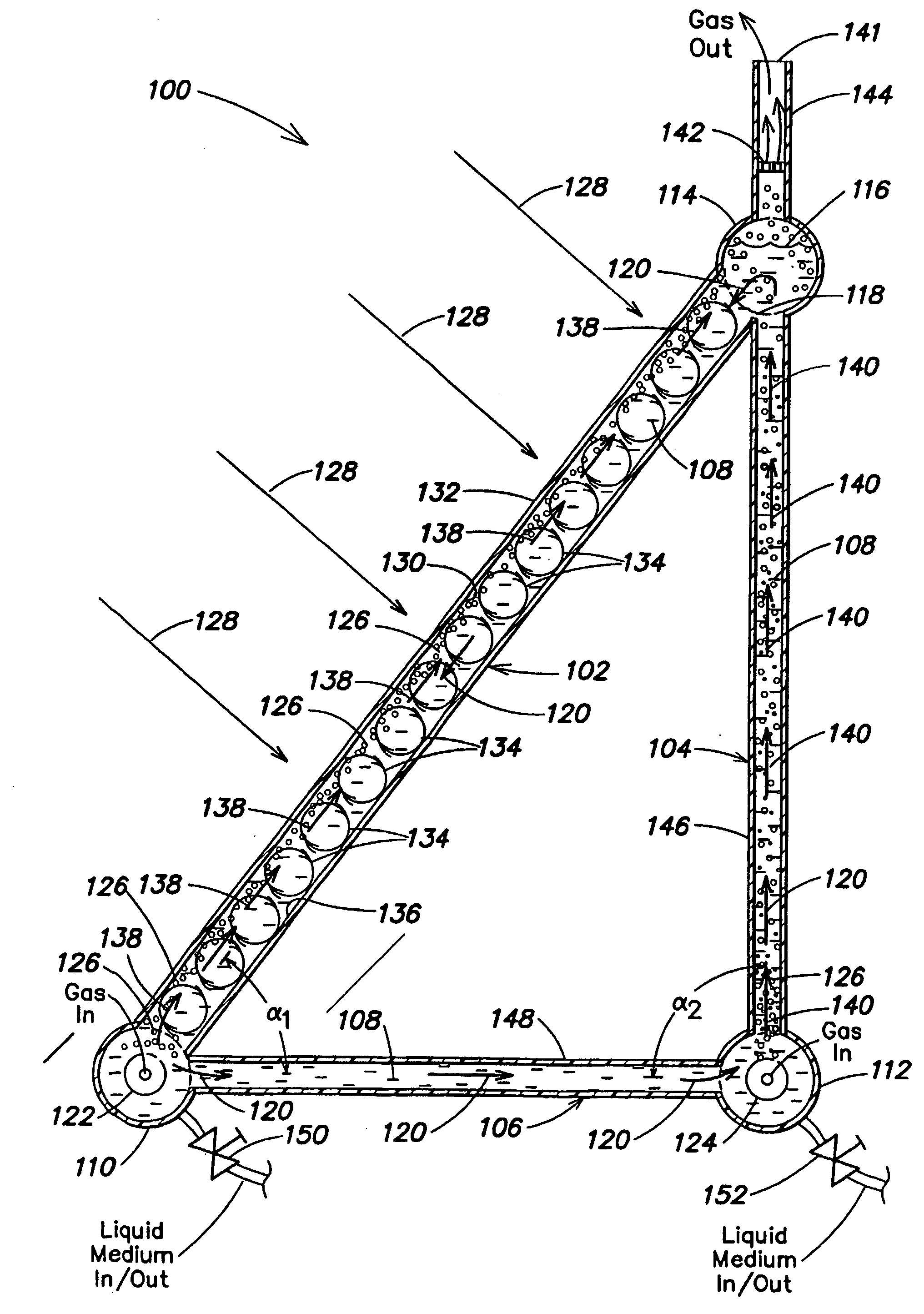
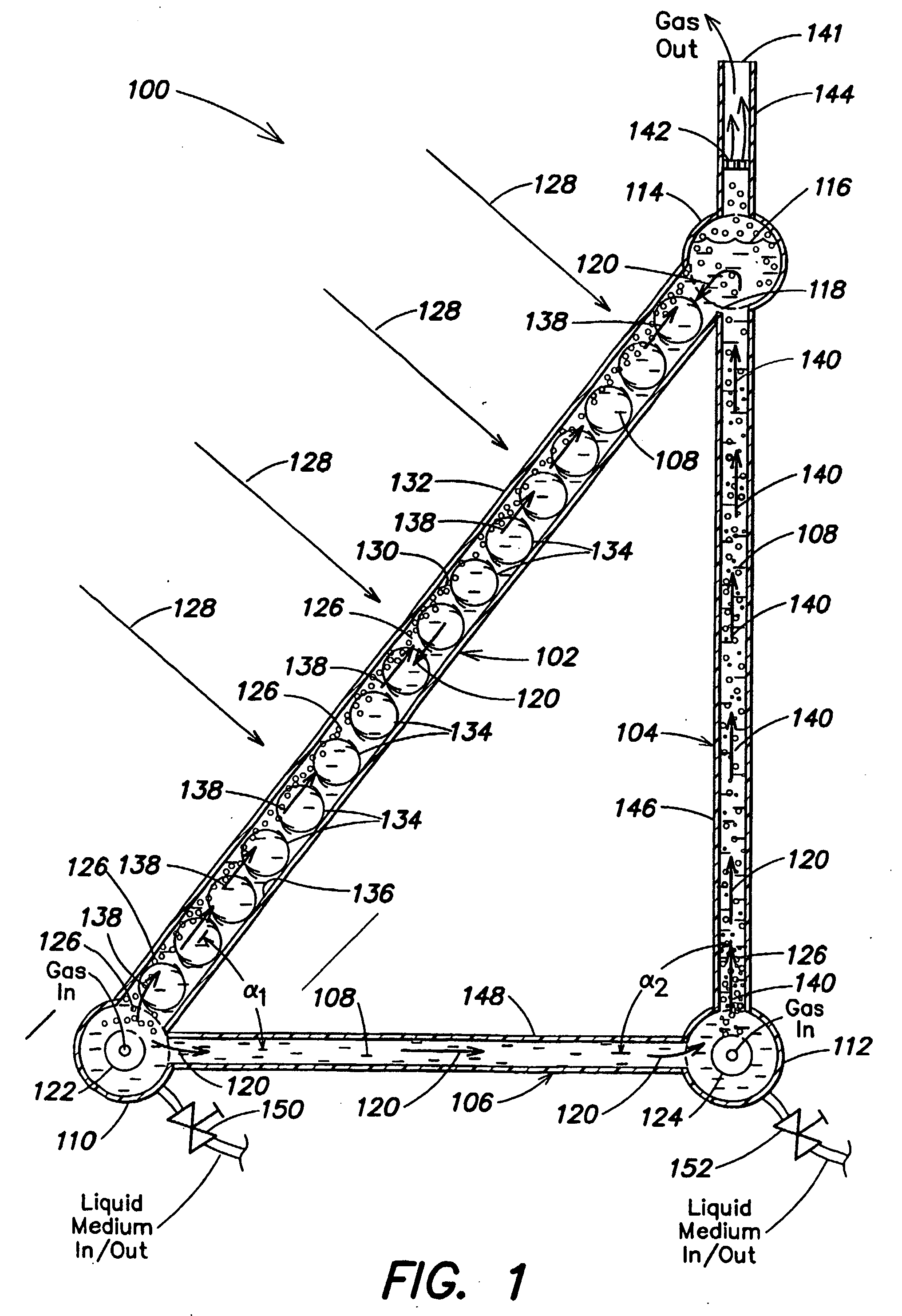
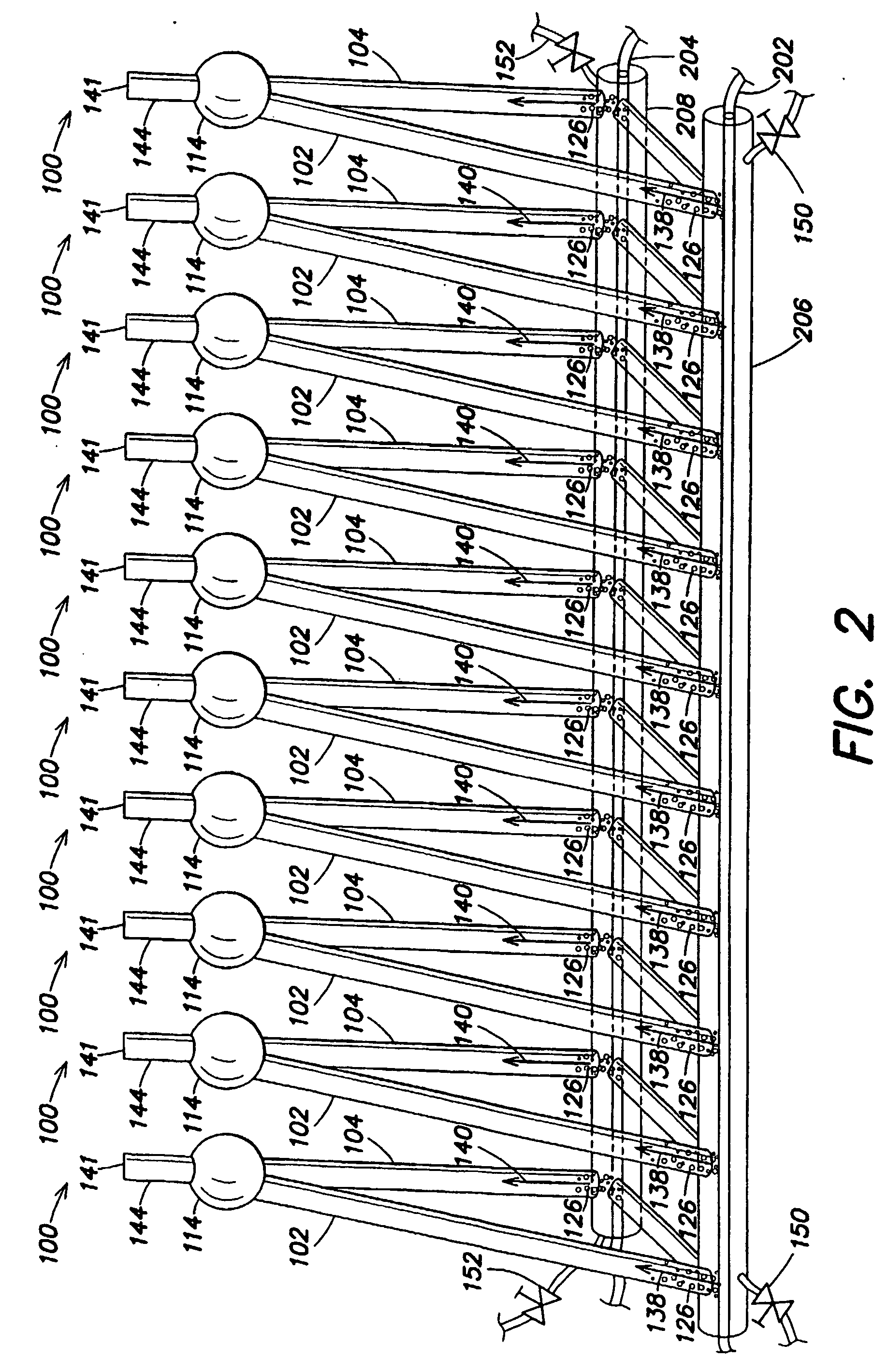
[0170] Each photobioreactor unit of the module utilized for the present example comprised 3 tubes of circular cross-section constructed from clear polycarbonate, assembled as shown in FIG. 1, with α1=45 degrees and α2=90 degrees. In this triangle, the vertical leg was 2.2 m high and 5 cm in diameter; the horizontal leg was 1.5 m long and 5 cm in diameter; and the hypotenuse was 2.6 m long and 10 cm in diameter. The photobioreactor module comprised 3 adjusted units arranged in parallel, similarly as illustrated in FIG. 2. This bioreactor module has a footprint of 0.45 m2

[0171] A gas mixture (certified, AGA gas), mimicking flue gas composition was used (Hiroyasu et al., 1998). The total gas flow input was 715 ml / min per each 10 liter photobioreactor in the module. Gas distribution to the spargers injecting gas into the vertical legs and the to the spargers injecting gas i...

examples 2-5

Photobioreactor Arrays for Mitigation of Power Plant Flue Gas Pollutants and Production of Algal Biomass

[0184] All examples below relate to a 250 MW, coal-fired power plant with a flue gas flow rate of 781,250 SCFM, and coal consumption of 5,556 tons / d. Flue gas contains CO2 (14% vol), NOx (250 ppm) and post-scrubbing level of SOx (200 ppm, defined in the US 1990 Clean Air Act Amendment). 12 h / d sunlight is assumed, and a mean value of solar radiation of 6.5 kWh / m2 / d, representing typical South-Western US levels (US Department of Energy). Algal solar efficiency of 20% is assumed, based on performance data of Example 1 and literature values (Burlew, 1961). Daytime algal CO2 and NOx mitigation efficiency is 90% and 98% (respectively), and at night 0% and 75% (respectively), based on Example 1 performance and literature values (Sheehan et al., 1998; Hiroyasu et al., 1998). Biodiesel production potential is 3.6 bbl per ton of algae (dry weight) (Sheehan et al., 1998). System size and p...


PUM

PropertyMeasurementUnit
wavelength rangeaaaaaaaaaa
wavelengthaaaaaaaaaa
diameteraaaaaaaaaa

Abstract

Certain embodiments and aspects of the present invention relate to photobioreactor apparatus (100) designed to contain a liquid medium (108) comprising at least one species of photosynthetic organism therein, and to methods of using the photobioreactor apparatus (100) as part of a gas-treatment process and system able to at least partially remove certain undesirable pollutants from a gas stream (608). In certain embodiments, the disclosed photobioreactor apparatus (100 can be utilized as part of an integrated combustion method and system, wherein photosynthetic organisms utilized within the photobioreactor (100) at least partially remove certain pollutant compounds contained within combustion gases, e.g. CO2 and/or NOX, and are subsequently harvested from the photobioreactor (100), processed, and utilized as a fuel source for a combustion device (e.g. an electric power plant generator and/or incinerator).

Description

RELATED APPLICATIONS [0001] This application claims priority under 35 U.S.C. § 119(e) to U.S. Provisional Application Ser. No.60 / 380,179, entitled “PHOTOBIOREACTOR AND PROCESS FOR MITIGATION OF FLUE-GASES,” filed on May 13, 2002, which is herein incorporated by reference in its entirety.FIELD OF INVENTION [0002] The invention relates generally to photobioreactors and processes to operate and use photobioreactors for the treatment of gases, such as flue gases. BACKGROUND OF THE INVENTION [0003] In the United States alone, there are 400 coal burning power plants representing 1,600 generating units and another 10,000 fossil fuel plants. Although coal plants are the dirtiest of the fossil fuel users, oil and gas plants also produce flue gas (combustion gases) that may include CO2, NOX, SOX, mercury, mercury-containing compounds, particulates and other pollutant materials. [0004] Photosynthesis is the carbon recycling mechanism of the biosphere. In this process, photosynthetic organisms,...

Claims


Application Information

Patent Timeline
Patent Type & Authority Applications(United States)
IPC IPC(8): C12M1/04B01D53/56B01D53/62B01D53/64B01D53/77B01D53/85C12M1/00C12M1/36
CPCB01D53/85C12M21/02C12M23/02C12M23/58C12M43/08C12M41/44C12M43/02C12M43/04C12M43/06C12M41/06Y02P20/59Y02A50/20
Inventor BERZIN, ISAAC
Owner GREENFUEL TECHNOLOGIES CORPORATION
Why Eureka
Try Eureka